 |
| Figure 1: Testing transmitter timing master jitter entails creating a track of TIE measurements |
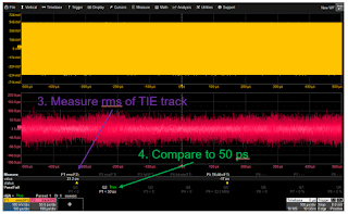
The test of transmitter timing master jitter uses test mode #2 (see the earlier post on the five test modes). Here, we will examine the RMS jitter of the medium dependent interface's (MDI's) output from the DUT over a period of at least 1 ms. We want to verify that the jitter on the transmitted clock is within the test limit of 50 ps.
To begin, we want to set up a time-interval error (TIE) parameter (see this link for more on TIE measurements). A thumbnail definition for TIE is the difference between actual and expected edge arrival times, which, as it happens, is not dissimilar to the essence of jitter.
Next, we want to create a track of TIE measurements. The track plot gives us insight into how the values change over time. A track plot shows each measured value in the acquisition. Figure 1 shows a zoomed-in view of an acquisition from the DUT's MDI output. We can see 13 TIE measurements plotted in the track that appears in the bottom display grid. Each of these measured values corresponds to a point on the acquisition: one for each edge. In this case, the maximum TIE value is 38 ps at TIE measurement 13. The track reveals that TIE is growing over time.
 |
| Figure 2: Checking the RMS value of the track of TIE measurements against the test limit of 50 ps |
The test of transmitter timing jitter with the DUT in slave mode calls for direct probing of the DUT's transmit clock (TX_TCLK). Optionally, this test can be approached by using the test mode #3 waveform. Either way, the object is to verify that the jitter on signals received by the slave is within the specified limit of 0.01 UI (150 ps). We will measure the RMS jitter of the slave device's TX_TCLK.
The specification indicates that each device must provide a means to access the transmit clock, but in the real world, this is rarely the case. Most devices are things like an ECU that's totally potted and enclosed. PHY evaluation boards are a different story, but the devices themselves are problematic. And without access to the TX_TCLK, this test cannot be performed. Again, the test mode #3 waveform may be used, but the letter of the specification calls for direct probing of TX_TCLK.
Methodology for this test is very similar to the use of test mode #2 in testing master jitter. We measure TIE, create a track plot of the TIE measurements, determine the RMS jitter of this track, and compare it to the specification's test limit of 150 ps.
Examining the TIE track plots can be revealing in many ways. Referring to the master jitter track of Figure 2, a cursory glance might seem as though there's little change over time but rather only randomness. But looking more closely, one can discern distinct lower-frequency behavior as well as a higher-frequency oscillation riding on top, and some even higher-frequency behavior. If desired, one might measure the frequency of these oscillations with help from cursors. Often, these behaviors can be traced back to something happening with the DUT, or perhaps its power supply.
Next time, we'll look at the most complicated of the Automotive Ethernet compliance tests: transmitter distortion.
No comments:
Post a Comment