 |
| Figure 1: This depicts the setup for the Automotive Ethernet transmitter distortion test |
The test makes use of the DUT's test mode #4 and introduces a disturbing sine wave that is sent to the device. That sine wave enables us to measure distortion as the DUT is subjected to it.
Figure 1 shows the diagram of the test setup from the specification. We send a sine wave, Vd, to the DUT and send the DUT's output into the oscilloscope. We want to ensure that the transmitted signal has distortion of no more than 15 mV so that the link partner's receiver has interoperability with the DUT. Note that the DUT, the oscilloscope, and the disturbing sine wave generator must all be synced with the DUT's transmit clock.
The disturbing sine wave generator simulates the presence of a remote transmitting device. If the DUT is not sufficiently linear, Vd will cause significant distortion products to appear in the DUT's output. The frequency of the disturbing sine wave must be exactly 1/6th of the DUT's symbol rate; in this case, it would be 11.1 MHz repeating. It also must have an amplitude of 5.4 Vpk-pk differentially.
 |
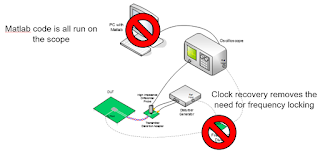
| Figure 2: Thanks to a software clock-recovery algorithm, there's no need for hardware frequency conversion |
Included in the specification is Matlab code for the computations. Any error from the ideal reference is considered to be distortion. The code looks to remove the disturbing sine wave and measure peak distortion at equally spaced phases of the symbol period. While this code can be run on a separate PC, Teledyne LeCroy embeds it in our oscilloscopes' software, negating the need for a Matlab license.
Earlier, we'd mentioned that setup for the distortion test is quite complicated and that the oscilloscope, sine wave source, and DUT all must be synced to the DUT's TX_TCLK, which runs at 66.666 MHz. All test equipment wants to see an external reference clock at 10 MHz. Thus, the issue at hand is the need to use a hardware frequency converter to upsample and then downsample the 66.666 MHz reference clock to 10 MHz.
To mitigate all of this complexity, Teledyne LeCroy brings to bear a software clock-recovery algorithm that handles the synchronization and does away with the hardware frequency converter (Figure 2). It also makes it possible to perform distortion tests on DUTs without access to the TX_TCLK; many real-world devices and systems, such as fully enclosed ECUs, do not bring out this signal at all.
 |
| Figure 3: Closeup of test setup for distortion test |
The signal from the DUT enters the text fixture at bottom right while the differential distortion sine wave enters at top center. SMA cables carry the signal to the oscilloscope for the test itself.
Software clock recovery is a two-step process that aligns the oscilloscope's sampled points with the DUT's TX-TCLK. The first step is to find the correct frequency offset of the DUT. We noted in an earlier post that the test of transmitter clock frequency has a tolerance of ±100 ppm. Now, we need to know the exact amount of that offset. To determine that number, we'll measure a reference waveform
 |
| Figure 4: This shows the repeating 2047-bit pattern of test mode #4 and its 30.075-μs period |
When ascertaining the frequency offset, we'll rely on the fact that the test mode #4 waveform comprises a repeating pattern of 2047 bits. Then, because we know the symbol rate of that waveform is 15 ns, we also know the waveform repeats itself every 30.075 μs. At the bottom of Figure 4 are zoom traces (in pink and yellow) shown to be separated by exactly that period.
 |
| Figure 5: Input data is resampled to the nominal bit rate by means of interpolation |
Using those interpolated points, we can either increase or decrease the frequency of the waveform. If we want to increase the frequency by 10%, we would sample every ninth point. Thus, from the initial sampling point, we would take the ninth, 18th, 27th, and so on from the interpolated waveform. Conversely, to decrease the frequency, we would take the 11th, 22nd, 33rd, and so on.
All of the foregoing is simply preparation for the actual distortion test itself, which entails calculating the amount of distortion using a Matlab processor onboard the oscilloscope. We take the measurement 10 times, comparing each to the distortion test limit of 15 mV to ensure passage.
In our next post, we will complete our detailed look at the Automotive Ethernet compliance test suite.
No comments:
Post a Comment