You need to test, we're here to help.

You need to test, we're here to help.
Showing posts with label pass-fail testing. Show all posts

13 June 2022

Oscilloscope Basics: Cal Out and Aux Out

Figure 5. New PCIe 6.0 compliance pattern signal.
Fig. 1: Cal Out and Aux Out 
provide many useful outputs.
Oscilloscopes are generally thought of in terms of the signals that are input to them, but even oscilloscopes that are not equipped with function/signal generators can usually output some useful test signals.

Nearly all oscilloscopes have a Cal Out (calibration output) terminal on the front. Most Teledyne LeCroy oscilloscopes also have an Aux Out (auxiliary output) connector on either the front or back, depending on  model. Both outputs provide configurable signals that can assist you to compensate probes and attenuators, test frequency response, trigger waveform acquisition and coordinate multiple test instruments.

20 September 2021

Testing Power Rail Sequences in Complex Embedded Systems

Figure 1. Four power rail signals on a single grid, with cursors measuring the time delay between the first pair in the sequence.
Figure 1. Four power rail signals on a single grid, with cursors
measuring the time delay between the first pair in the sequence.
Embedded computing systems generally require multiple supply voltages to deliver power to the microprocessor, memory and other on-board devices. There is usually a 12- or 15-volt DC primary supply, and numerous buck or boost converters working off the primary to help provide various voltages throughout the embedded system. Most microcontrollers have a prescribed order in which the voltages must be applied to prevent problems like lockups, so an area of concern when designing deeply embedded systems is the proper sequencing of power rails as they power up or down. Power management IC’s (PMIC) or power sequencers perform many of the sequencing tasks, but during validation and when troubleshooting, the order and timing of the power sequence should be verified.

18 July 2017

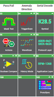
The Periodic Table of Oscilloscope Tools: Analyze (Part I)

Analysis tools deepen insight into waveform behavior and relationships
Figure 1: Analysis tools deepen
insight into waveform behavior
and relationships
The path from problem to solution via oscilloscope moves through a number of stages. Doing so involves capture of a signal, determining how it's to be viewed, taking measurements of various parameters, and possibly applying math functions to the waveform. All of these stages depend on the roster of tools that the oscilloscope brings to bear on the process. Teledyne LeCroy's Periodic Table of Oscilloscope Tools represents our view of the world of such tools.

18 June 2014

Applying Selective Averaging to Waveform Acquisitions

Figure 1: Using pass/fail testing to average only those waveforms which are inside the tolerance mask
Figure 1: Using pass/fail testing to average only those
waveforms which are inside the tolerance mask
In the course of using an oscilloscope, there are likely to be times when you'd like to separate pulses based on wave shape or some parametric value and average only those pulses that meet some criteria. Teledyne LeCroy's oscilloscopes, and others, provide pass/fail testing using masks and/or parametric readings to qualify waveforms before they're added into an average or other processing function. Let's take a look at how this works on a Teledyne LeCroy oscilloscope.