 |
Figure 1: DDR test configuration
for a desktop computer |
Since its inception as a standard in the mid 1990s, dual data-rate (DDR) SDRAM memory has been near ubiquitous in computing applications. Compared to single data-rate SDRAM, the DDR SDRAM interface makes higher transfer rates possible by more strict control of the timing of the electrical data and clock signals.
Implementations often have to use schemes such as phase-locked loops and self-calibration to reach the required timing accuracy. The interface uses double pumping (transferring data on both the rising and falling edges of the clock signal) to lower the clock frequency. The name "double data rate" refers to the fact that a DDR SDRAM with a certain clock frequency achieves nearly twice the bandwidth of a SDR SDRAM running at the same clock frequency, due to this double pumping.
 |
Figure 2: A typical DDR test setup
for a netbook computer |
The strict control of clock and data timing leaves relatively little margin for error in a DDR SDRAM interface. Testing of these interfaces demands adherence to some important best practices to ensure accurate and repeatable results. Let's look at a few of these best practices, beginning with some recommended mechanical probing techniques.
First, what does a typical DDR test configuration look like? Figure 1 shows an example of a test configuration for a desktop computer platform while Figure 2 shows the setup for a netbook computer. Refer to the images (click on them to enlarge) for some notes on the setups.
 |
Figure 3: Using probe holders
in reverse position |
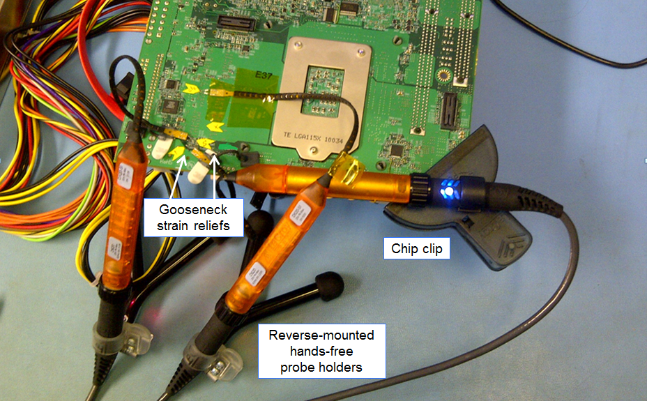
The first recommended technique makes use of a hands-free probe holder mounted in reverse position (Figure 3). This configuration provides much-needed strain relief for the probe connections. The probe holder acts as a counterweight, removing force from the probe tip. Another recommended technique for strain relief is to employ a gooseneck device to support the probe tips. This is achieved by mounting an adhesive base on a chip in close proximity to the DUT. A third technique is to use a chip clip to secure a probe to a board or chassis. The clip prevents movement of the probe platform's cable assembly.
Figure 4 shows all three of the above techniques in use. The combination of the chip clip, probe holders, and gooseneck strain reliefs do an excellent job of preserving the integrity of the probe connections while probing DDR clock, strobe, and data signals.
 |
Figure 4: Deployment of chip clip, reverse probe holders,
and gooseneck strain relief |
Yet another best practice is to completely secure the probing area with tape so as to immobilize the probe connections and protect them from outside impact. This is especially recommended if the test setup needs to be shipped or otherwise transported from one location to another. It ensures that the solder-in leads are firmly secured and electrical connections remain intact. The same approach should be used if testing, say, a DDR4 DIMM. The probes should be soldered and taped down before the module is inserted into its slot on the motherboard.
If one were to be transporting such a test setup on a rolling cart within the same facility, it's a good idea to place an ESD bag underneath the DDR DUT for static protection. Using a cart is recommended as it provides support for the three probe-platform cable assemblies (one each for clock, strobe, and data lines). For extra security, one might anchor the assemblies to the card with cable ties, clips, or tape. Don't forget to carefully label probe tips with adhesive labels; the probe amplifiers will be disconnected during transport and the labels will help with reconnecting the probes. It's not a bad idea to label the probing points on the DUT as well.
Stay tuned for more best practices for eliminating DDR test pitfalls in future posts.


No comments:
Post a Comment