 |
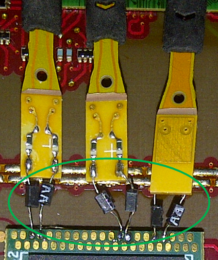
| Figure 1: Damping resistors on solder-in probe tips |
Having said that, there are also some things to watch out for; call them "worst practices" if you like. These no-nos can adversely impact measurement accuracy or even wreck your probing setup.
The first item on the list is less of a "worst practice" and more of an item that should be carefully considered. Many solder-in probes are equipped with damping resistors. The question is whether these damping resistors should be removed when accessing signal lines through a chip interposer.
 |
| Figure 2: An eye-diagram comparison |
However, there are some disadvantages of removing the resistors. For one thing, this constitutes a modification of the probes. The old tips and resistors are removed and must be replaced with new leads. For another, once this modification has been done, the probes can't be used for other applications or for general-purpose uses until the resistors and leads are reattached to the probe-tip PCB.
 |
| Figure 3: Use #34 wire to replace probe tips if you remove damping resistors |
Another thing to watch out for in DDR testing: Be careful about using square-pin or other adapters. Their use will adversely affect the rated bandwidth of your probe, thus reducing measurement accuracy. This won't be a problem, though, if you are testing low-speed-grade DDR signals.
Finally, referring back to our first post in this series on best practices for DDR testing, the solder-in probe interfaces are relatively fragile. Make sure you use hot glue, tape, probe holders/clips, some other sort of strain relief, or some combination of these techniques. Otherwise, even a small inadvertent impact to the target board could dislodge the connections. Using strain relief is practically mandatory for solder-in tips in any application, not just DDR testing. You soldered down those tips once, so why risk the need to do it again?
No comments:
Post a Comment