The USB Type-C® connector is designed to be very simple for the user to use: you insert it in either orientation, and a multitude of services just “work”. Though simple to use, it is a complicated connector to program and test, with a very complex system of protocols behind it. There is USB power delivery (USB-PD) and multiple rates of USB data delivery from USB 2.0 through USB4®, specified by the USB Implementers Forum (USB-IF®). There are protocols other than USB, such as DisplayPort™, High-Definition Multimedia Interface (HDMI™), Peripheral Component Interconnect Express (PCIe®), Base-T Ethernet and Thunderbolt™.
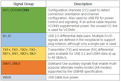
So, what actually happens when you connect a USB-C cable? To understand that, first let’s take a look at the signals and pin assignments in the USB-C connector receptacle (Figure 1).
 |
Figure 1: The USB-C receptacle pin assignments showing the key signals used for device-to-device communications. Related pins have matching color overlays. |
 |
| Table 1: USB-C connector signal groups. |
Okay, now that you have some idea of what we’re working with, let's talk a bit about what happens when you connect a USB Type-C cable. Since either piece of hardware on either end of the cable could potentially be a Host or a Device, a power supplier (Source) or a power consumer (Sink), the USB-C receptacle, plug and cable undergo a configuration process over the configuration channels (CC1 and CC2) to determine some basic functionality of the cable:
- Source-to-Sink attach/detach
- Plug orientation/cable twist
- Initial power (Source-to-Sink) and data (Host-to-Device) relationship
- If the cable is an active cable that requires VCONN
- USB Type-C VBUS current and usage
- USB-PD communication
- Configuration of as-yet-undefined functional extensions
First, CC1/CC2 are used by a host or hub port to detect an attach when one of the pins senses a specified resistance to ground (GND). The detach is detected when the same pin is no longer terminated to GND. This also determines the plug orientation and therefore the channel configuration: are we transmitting on the TX1 pair in A2 and A3, or the TX2 pair in B2 and B3, and so forth?
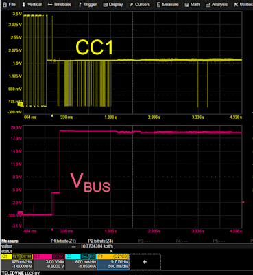
Once the connection is established, the host port provides a default 5 volts of initial power on the VBUS line. With initial power available, an active cable’s need for supplemental VCONN power is detected, which is supplied via the unused CC line.
 |
| Figure 2: The initial 5 V power setting of the VBUS line, followed by the negotiation of the power contract (20 V) via the CC1 signal line. |
We now come to data mode link training. This process defines the actual communication that's going to be happening over the USB-C cable, since either system on either end can be capable of communicating via any number of protocols at different speeds, just as humans can speak multiple languages with different degrees of fluency. There is a broad range of communication options, each of which has its own link training process. The most basic is USB 2.0, which is negotiated using the D+ and D- data lanes. There is also USB 3.2, which is negotiated using high-speed ordered sets over the TX and RX lanes.
USB4 link training involves a complex state machine, with sideband management and training substate negotiations conducted over the AUX channel (differential sidebands SBU1 minus SBU2), and data negotiations using ordered sets over the Tx and Rx lanes. The sidebands are bidirectional, half-duplex channels that run at a rate of 1 Mbps. The Tx/Rx lanes are differential pairs forming a unidirectional, high-bandwidth channel used to transport video and audio signals.
The USB4 specification supports alternate modes (alt-modes) for high-speed data transfer over the USB-C cables, which enables interoperability across a multitude of devices. The protocols supported in alt-mode include HDMI, DisplayPort, PCIe, Ethernet and Thunderbolt. For DisplayPort alone, there are three different standards that define how a link is made when using DisplayPort over Type-C.
 |
| Figure 3: The sequence of signal events during the initialization of a DisplayPort alt-mode connection. The USB-PD signal shows activity on the CC line. The DP-AUX signal shows the SBU lines. |
Once alt-mode is initiated, the DisplayPort link training process begins over the SBU lines using DP-AUX protocol, as defined by the VESA DisplayPort over USB Type-C specification. New pin assignments are established, and whether the cable will operate as four lanes of DisplayPort, or what is called a 2x2 type that supports two lanes of DisplayPort and a path for USB 3.2 high-speed data. The AUX channel continues with the training of the physical layer for DisplayPort, including DisplayPort configuration data like copy protection (HDCP) and device identification (EDID).
At last, the main link transmissions of DisplayPort data are negotiated as defined by the VESA DisplayPort main specification. This uses the SBU lines differentially (i.e., SBU1 minus SBU2) for link training, then the Tx/Rx lanes for data transactions.
If the implementer has opted to include a lane of USB 3.2 with your DisplayPort, that also undergoes its own main link training over the Tx/Rx lanes, before commencing data transactions.
Remember, each of these negotiations that occur after you plug in a USB-C cable utilizes different standards, each with its own protocol and physical-layer test requirements, published by different certifying organizations. So, you can see that behind the USB-C connector is a lot of technology keeping it simple for the user, but difficult for the implementer. Fortunately, Teledyne LeCroy has everything implementers need to keep USB-C data flowing, from physical-layer decoders, to electrical compliance test software, to fixtures that enable you to analyze live links, to USB protocol analyzers and exercizers.
Learn more in the on-demand webinar, "Introduction to USB Type-C Physical Layer Testing."
No comments:
Post a Comment