You need to test, we're here to help.

You need to test, we're here to help.
Showing posts with label USB-PD. Show all posts

06 June 2022

What Happens When You Connect a USB-C Cable

The USB Type-C® connector is designed to be very simple for the user to use: you insert it in either orientation, and a multitude of services just “work”. Though simple to use, it is a complicated connector to program and test, with a very complex system of protocols behind it. There is USB power delivery (USB-PD) and multiple rates of USB data delivery from USB 2.0 through USB4®, specified by the USB Implementers Forum (USB-IF®). There are protocols other than USB, such as DisplayPort™, High-Definition Multimedia Interface (HDMI™), Peripheral Component Interconnect Express (PCIe®), Base-T Ethernet and Thunderbolt™. 

So, what actually happens when you connect a USB-C cable? To understand that, first let’s take a look at the signals and pin assignments in the USB-C connector receptacle (Figure 1).
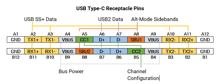
Figure 1: The USB-C receptacle pin assignments showing the key signals used for device-to-device communications. Related pins have matching color overlays.

Figure 1: The USB-C receptacle pin assignments showing the key signals used for device-to-device communications. Related pins have matching color overlays.

13 December 2021

USB4 Alt-Mode Testing: DPAUX and USB-PD

Figure 1: The interfaces that make up the USB-C connector and their relationships.

The USB Type-C® (USB-C) connector supports not only USB data transfers at speeds of up to 20 Gb/s but also can be reconfigured to support a wide variety of other interfaces through the USB4 provision for alternative (Alt) modes. The Alt-Mode protocols supported include Thunderbolt™, Mobile High-Definition Link (MHL), Peripheral Component Interconnect Express (PCIe®), High-Definition Multimedia interface (HDMI®) and DisplayPort™ (DP).

The diagram of the USB-C receptacle in Figure 1 shows where it potentially switches from normal operation into Alt-Mode.

22 March 2021

TDME Primer: Automated Timing Measurements of USB-C Protocols

Figure 1: Interleaved decoding of USB-PD and DP-AUX signals.
Increasingly, serial data analysis is analysis of the interoperability of the many protocols that must perform together within interconnects and embedded systems. Nowhere is this more true than for USB-C® devices, which we’ll focus on in this post, although these examples of cross-protocol timing measurements could apply to any two protocols supported by our TDME and DME options.

The USB-C connector packs many protocols onto one, small pin set, and maintaining signal and power integrity is a compliance challenge. Besides high-speed data delivery, USB-PD (power delivery) provides flexible power distribution, while auxiliary sideband signals, like DisplayPort™, transport video. Troubleshooting these capabilities requires the ability to measure timing between serial data packets, as well as between data packets and analog signals. 

For example, DisplayPort over USB-C (DPoC) in alternate mode (alt-mode) can manifest as an interoperability failure if there is a timing issue between alt-mode initiation and the start of DP-AUX.