You need to test, we're here to help.

You need to test, we're here to help.

30 July 2014

Video: WaveSurfer 3000 and the MAUI User Interface

Oscilloscopes are often an engineer's best friend, but that can change depending on how easy or difficult a given instrument is to use. Sure, the oscilloscope's capabilities and technical specs are critical, but if the machine is difficult or non-intuitive to interact with, the user ends up wasting time figuring out what should be simple.

24 July 2014

How Many Channels is Enough?

Figure 1: A switch-mode power supply driving a fixed load can be designed and optimized specifically for that load.
Figure 1: A switch-mode power supply driving a fixed load
can be designed and optimized specifically for that load.
The bulk of oscilloscope applications are well served by instruments with four analog input channels. Most basic debugging and design-related work involves probing of only one signal at a given time, and occasionally more than one, especially when differential signals are concerned. Thus, many users may never see a need for an oscilloscope with more than four channels.

Having said that, there are some applications that by their very nature surpass four channels. Moreover, some of these applications concern circuits and devices that are produced in extremely high volumes. A case in point is switch-mode power supplies, such as those typically found in notebook PCs, tablets, or embedded systems.

18 June 2014

Applying Selective Averaging to Waveform Acquisitions

Figure 1: Using pass/fail testing to average only those waveforms which are inside the tolerance mask
Figure 1: Using pass/fail testing to average only those
waveforms which are inside the tolerance mask
In the course of using an oscilloscope, there are likely to be times when you'd like to separate pulses based on wave shape or some parametric value and average only those pulses that meet some criteria. Teledyne LeCroy's oscilloscopes, and others, provide pass/fail testing using masks and/or parametric readings to qualify waveforms before they're added into an average or other processing function. Let's take a look at how this works on a Teledyne LeCroy oscilloscope.

09 June 2014

Video: Vertical Controls on the HDO Oscilloscopes

Here's another in our continuing series of tutorial videos. This time, we'll review the use of the vertical controls on a Teledyne LeCroy HDO oscilloscope. These controls facilitate positioning and scaling of waveforms vertically on the oscilloscope's display. Note that although we're demonstrating these controls on an HDO, you'd be rather hard pressed to find an oscilloscope from any manufacturer without a volts/div and vertical offset control. Thus, this video is applicable to whatever oscilloscope you have on your bench.

There are quite a few tutorial videos for a broad range of Teledyne LeCroy products on our YouTube channel. Head on over whenever you need a refresher!


22 May 2014

The Effects of Passive Probe Ground Leads

Teledyne LeCroy's PP108, a representative passive probe
Figure 1: Teledyne LeCroy's PP108,
a representative passive probe
When you open the box containing your shiny new oscilloscope, one of the items you'll likely find inside is a set of basic 10:1 passive probes (Figure 1). Those probes have a ground lead that you'll want to use when you make measurements. Your probe has a bandwidth specification that's probably somewhere between a few hundred megahertz to 1 GHz; that spec was obtained at the factory with a specialized test jig having a specific ground inductance and source impedance. Now, the way in which you connect your ground lead can have a big impact on the real-world bandwidth and response of the probe.

15 May 2014

Back to Basics: S-parameters
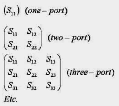
S-matrices for one-, two-, and three-port RF networks
Figure 1: S-matrices for one-, two-,
and three-port RF networks
Suppose you have an optical lens of some sort onto which you shine a light with a known photonic output. While most of the incident light passes through the lens, some fraction of the light is reflected and some is absorbed (the behavior is also dependent on the wavelength of the incident light). You'd like to characterize that lens: Exactly how much light was reflected? How much passed through? What is it about the lens that prevented all of the light from passing through?

16 April 2014

Is Your Testbench Mixed-Signal Ready?

A representative block diagram of a mixed-signal embedded system
Figure 1: A representative block diagram of
a mixed-signal embedded system
Mixed-signal design is ubiquitous these days, with hybrids of digital and analog circuitry turning up everywhere. A typical mixed-signal designer may be a hardware or software engineer with specific needs. They may be working with 4-bit, 8-bit, 16-bit, and 32-bit microcontrollers in a single embedded controller or across several embedded systems. They need to capture a host of different signal types and serial-data protocols and understand timing relationships between them. Then there's all the different sensor signals, power-supply signals, and PWM control signals to guarantee embedded system performance and reliability.