 |
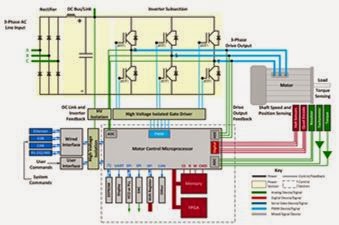
| Figure 1: This image depicts the complete design and debug challenge posed by a variable-frequency motor drive |
As noted earlier, these are the essential elements comprising a VFD's power conversion section:
- Input-output voltage ratings
- DC bus (or link) topology
- Power-semiconductor components found in the inverter subsection
- Inverter subsection technology
- (Gate-drive) pulse-width modulation (PWM) techniques
- Motor drive control architecture and algorithms
The function of the DC bus (or link) is to store energy for input to the inverter subsection. The DC bus must store enough energy so that the bus is "stiff" and doesn't allow appreciable voltage sag when under load. Ripple on the bus could mean an inadequate mains supply, poor inverter design, or issues with inverter operation. It's common to monitor the DC bus ripple for correlation with other VFD behaviors.
There are three main topologies for the DC bus:
- Voltage-sourced inverter (VSI)
- Current-sourced inverter (CSI)
- Load-commutated inverter (LCI)
Current-sourced inverters store current in an inductor. Response times of a CSI are slower than that of a VSI owing to a delay in current delivery from the inductor to the inverter subsection's input.
A load-commutated inverter uses thyristors (SCRs) and cannot use PWM signaling for the output voltage. It's fallen largely out of use with the advent of IGBTs of higher power and voltage.
The matrix converter (or cycloconverter) is a fourth type that dispenses with the DC bus and uses a direct connection between the AC-rectified output and the inverter input. This topology sees use in high-voltage power line switching or frequency conversion.
Motor-drive inverter subsections use various kinds of power-semiconductor devices, generally either MOSFETs or IGBTs. MOSFETs are typically found in 240-V AC and lower input drives while IGBTs are used in input drives of 380 to 600 V AC. Devices using wide-bandgap materials such as silicon carbide (SiC) or gallium nitride (GaN) have faster rise times and are seeing more use in motor drives for efficiency's sake. Analysis of switching and conduction losses of these devices calls for higher-bandwidth voltage and current measurements. When measuring drive outputs, lower bandwidth is usually sufficient, as the highest speed wide-bandgap materials are not typically driven at their highest speeds due to reliability and/or EMI/RFI emissions concerns.
The VFD inverter subsection topologies break down like this: Single-phase VFDs use H-bridge topologies, while three-phase VFDs use cascaded H-bridge topologies. Both result in two-level output signals. Other topologies produce more than two levels of output. Most VFDs in the 600-V class and lower motor applications are using two-level, cascaded H-bridge topologies.
In the next post in this series, we'll look at pulse-width modulation techniques.
No comments:
Post a Comment