 |
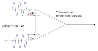
| Figure 1: Differential-mode dynamic range is the maximum allowable voltage between the probe amplifier's inputs |
The three types of dynamic range are:
- Input differential-mode dynamic range
- Input common-mode dynamic range
- Input offset range
Your probe must have enough of each of these three types of dynamic range to sample the signal at the probing point and be able to center the signal on the oscilloscope's display.
Differential-Mode Dynamic Range
Differential-mode range, simply put, is the maximum allowable voltage between the positive and negative terminals of the probe amplifier (Figure 1). It's taken for granted that any signal that fits within the differential-mode dynamic range can be amplified by the differential-mode amplifier without clipping. Hence, this parameter is sometimes referred to in a general sense as the probe's "dynamic range." But it is also important to account for the other two varieties of dynamic range referred to above.
Exceeding the probe amplifier's differential-mode dynamic range will have the same effect as overloading a single-ended amplifier. The output will go to the rail voltage and stay there. Because the differential-mode signal is the voltage being measured, it's usually easy to see on the oscilloscope's display that the differential-mode dynamic range has been exceeded. Amplifier gain and input attenuators will directly scale the differential-mode dynamic range.
Common-Mode Dynamic Range
 |
| Figure 2: Common-mode dynamic range is the maximum allowable voltage from either input to ground |
Because the common-mode component is not processed by the amplifier, the amplifier gain does not scale the common-mode range. The common-mode range is scaled by any external attenuators.
 |
| Figure 3: Input offset range is the maximum differential offset that a probe can apply to an input signal to bring it within the oscilloscope's differential-mode dynamic range |
Input Offset Range
Our next installment will continue examining the topic of probe dynamic range. Meanwhile, please visit the prior entries in this series of posts:
Probing Techniques and Tradeoffs (Part I)
Probing Techniques and Tradeoffs (Part II)
Probing Techniques and Tradeoffs (Part III)
Probing Techniques and Tradeoffs (Part IV)
Probing Techniques and Tradeoffs (Part V): Probe Loading
No comments:
Post a Comment