 |
| Figure 1: The two basic PCIe 4.0 transmitter tests are shown above outlined in green |
The first thing to say about PCIe 4.0 transmitter electrical tests is that we cannot tell you about all of them. That's because one of them, namely the transmitter pulse-width jitter test, is new for this fourth generation of the test standard and is still being defined by PCI-SIG. When we do have more on that specific test, we will pass it on in an update.
 |
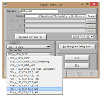
| Figure 2: SigTest software, still under development, is required for PCIe 4.0 transmitter testing |
Both of the transmitter tests must be performed not with the oscilloscope's internal test software, but rather with SigTest (Figure 2), which is software that will become available from PCI-SIG At this time, SigTest is still under development and is available only to the test-development subgroup.
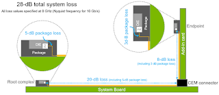
Before we begin discussing the actual tests, it's incumbent on us to first describe the PCIe 4.0 nominal channel (Figure 3), which comprises the elements we'll be testing. On the system board (or motherboard) is what's termed the "root complex," which may be, for example, a Tx/Rx block within the system processor. From that physical location on the system board, the channel proceeds to the edge-card connector, which in PCIe 4.0 terminology is known as the Card ElectricalMechanical (or CEM, say "chem") connector. From there, the channel continues on the add-in card that's plugged into the CEM connector and makes its way to the "endpoint," which may be another Tx/Rx block within the add-in card's processor chip.
 |
| Figure 3: The PCIe 4.0 nominal channel must have a total system loss of no more than 28 dB |
On the system board, the maximum allowable channel loss is 20 dB, and that number includes a 5-dB loss within the "root complex" package. On the add-in card, maximum allowable channel loss is 8 dB, with 3 dB of that residing within the "endpoint." That makes for a 28-dB maximum allowable end-to-end channel loss.
Bear in mind that a PCIe 4.0 channel can (and ideally should, in the interest of signal fidelity) have total system loss of less than 28 dB, which would buy you margin. Note that these channel-loss decibel values are defined at 8 GHz, which is the Nyquist frequency for a 16-Gb/s serial data signal.
 |
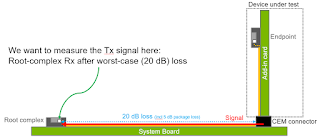
| Figure 4: Assuming the DUT is an add-in card, the transmit signal is measured at the root-complex receiver |
Assuming that the DUT is an add-in card, it's apparent that the signal at the CEM connector will suffer another 20-dB loss after it exits the add-in card before it reaches the receiver at the root complex, which is the physical location at which we want to evaluate the transmit signal. This is the scenario we want to simulate for a transmitter signal-quality test (Figure 4).
Our next post will begin a close look at the PCIe 4.0 transmitter tests themselves.
Earlier posts in this series:
Introduction to PCIe 4.0 Electrical Compliance Test
Gearing Up for PCIe 4.0 Electrical Compliance Test
2 comments:
best
Excellent information you have shared, thanks for taking the time to share with us such a great article.
MCC Panel Manufacturers
Post a Comment