 |
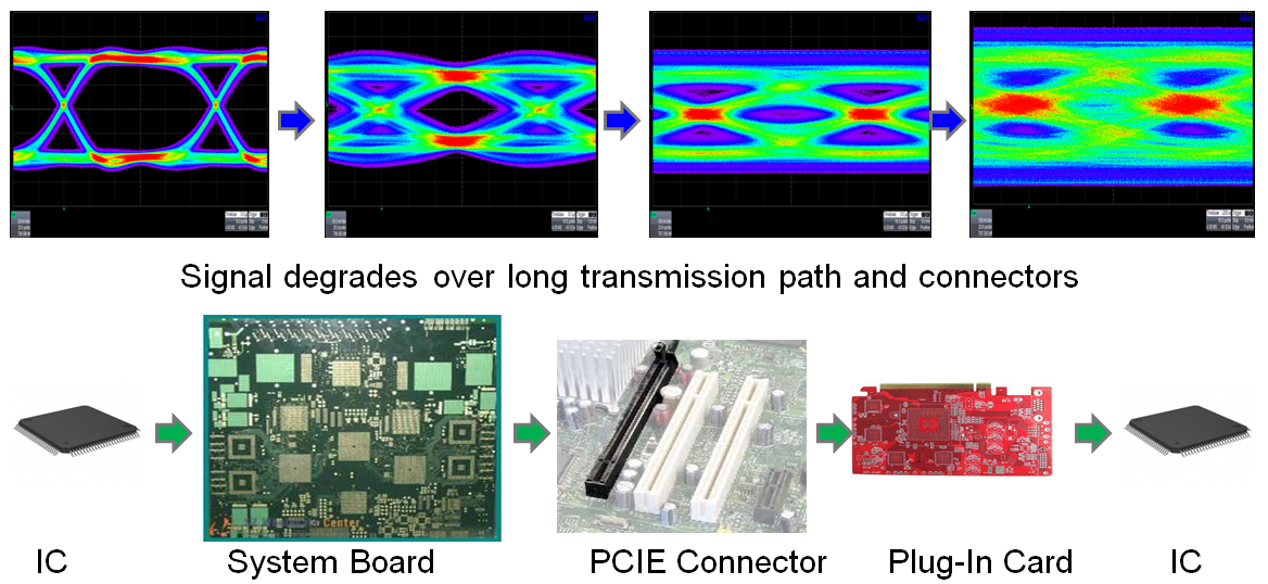
| Figure 1: SI problems are the root cause for dynamic link equalization in PCIe 3.0 |
The current version of the PCIe specification, 3.0, brought some notable improvements over PCIe 2.0. Bit rates rose from 5 GT/s to 8 GT/s (effective bit rates of 4 Gb/s per lane and 7.88 Gb/s per lane, respectively). However, for products to exhibit compliance to the spec and garner the coveted PCIe logo, receiver testing, which was deemed "informative" for PCIe 2.0, became a requirement in PCIe 3.0.
Perhaps the biggest change from PCIe 2.0 to PCIe 3.0 other than the bit rate was the requirement for dynamic link equalization. The main reason why dynamic link equalization becomes so critical in PCIe 3.0 is because even though the bit rate was bumped up, the specification for the transmission path, i.e. connectors, remained constant. In fact, the PCIe transmission path spec hasn't changed since PCIe 1.0, when the bit rate was 2.5 GT/s. At that speed, little emphasis was placed on signal integrity concerns.
 |
| Figure 2: Making PCIe 3.0 work requires equalizers at the transmit and receive ends of the channel |
The answer to this conundrum is equalizers. With signal equalizers either before, after, or (most typically) at both ends of the channel, the anomalies in the signal are compensated for and the channel hits the PCI-SIG's required bit-error rate of at least 10-12 (Figure 2). Transmit-side equalization (referrred to as TxEQ) comes in the form of de-emphasis and preshoot , while receive-side equalization (known as RxEQ) takes the form of continuous-time linear equalization (CTLE) and decision feedback equalization (DFE).
In principle, what happens to degrade PCIe signal integrity is that the channel acts on the signal as if it were a low-pass filter by attenuating the higher-frequency components. The equalization does the inverse by boosting those high-frequency components.
Next time, we'll look more closely at these equalization techniques and how they function.
No comments:
Post a Comment