 |
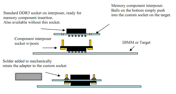
| Figure 1: The anatomy of a chip interposer |
If you're a PCB layout designer, you've probably heard one or more test engineers complain: "Why can't you lay out the board so that it can be tested?" All too often, components that need to be accessible to oscilloscope probes are physically inaccessible, whether it's because of close proximity of adjacent components or ball grid array (BGA) mounting of the DUT. It's nearly always a necessary evil, though, because of PCB cost and/or mechanical constraints.
 |
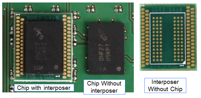
Figure 2: This series of photos illustrates how the interposer
brings out the DDR BGA's I/Os to make them
accessible to test probes. |
So say you need to get probes onto a dual data-rate (DDR) memory device and some (or all) of the pins are inaccessible. Here is where chip interposers come in. Chip interposers are designed for probing extremely close to memory components and are essential for just these situations (Figure 1). Interposers are installed by soldering the bottom side of the device to the DDR BGA footprint on the target board where the memory component would be soldered. The memory component is then soldered to the top side of the interposer (Figure 2). Interposers can be most useful in embedded applications and in those where there are chips on both sides of a dual in-line memory module (DIMM).
 |
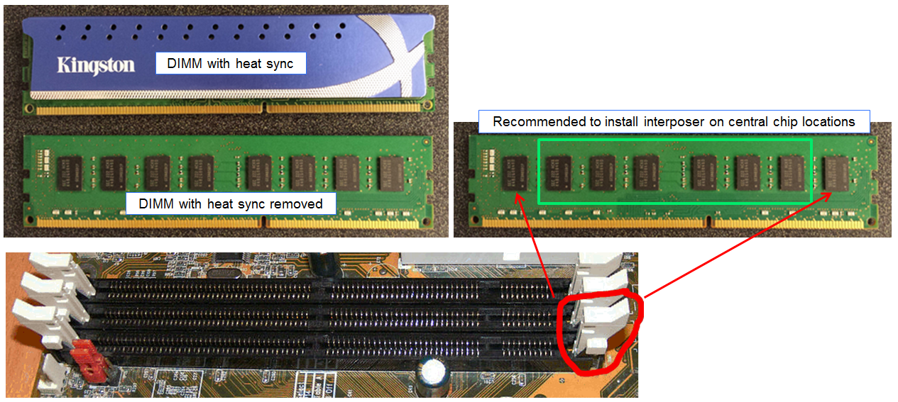
Figure 3: Be careful when using interposers with DDR
DIMMs. Avoid using them on the chips in the end
locations, where they may interfere with latches. |
As helpful as chip interposers can be in testing DDR BGAs mounted on a board, be careful with them when it comes to DIMM applications. As Figure 3 illustrates, installation of interposers on the far right- and left-hand chips on a DIMM could interfere with latching of the side clips that secure the DIMM in its board-mounted connector. Thus, it's recommended that interposers be installed on the six central chip locations and not in the end locations.
In addition to the aforementioned strategy regarding DIMMs, another "best practice" for testing with interposers is to use tweezers to manipulate probe tips when soldering. Tweezers are more nimble than most peoples' fingers, providing better placement and accuracy during the soldering process.
Another tip: Solder probe tips to the interposer in advance. It's easier than when the interposer is in place, and the soldered-in tips can be switched in and out as necessary for connection to a probe amplifier.


2 comments:
Glad to read about Memory Testing Part. Thanks for sharing the blog.
Hi. Would you have an idea where can I buy such an interposer? Thanks.
Post a Comment