The diagram of the USB-C receptacle in Figure 1 shows where it potentially switches from normal operation into Alt-Mode.
In normal USB operation, the USB-Power Delivery (USB-PD) interface allows devices to negotiate who is the Source and the power level supplied between the Source the Sink (Rx) using the VBUS (A4/B4 and A9/B9) and ground pins. USB-PD is also responsible for Hot Plug Detect (HPD) and Interrupt Request (IRQ) operation. HPD allows the Source to detect the presence of Sink. The IRQ function permits the Sink to notify the Source of status changes. The power contracts between devices are negotiated using the Channel Configuration (CC1 and CC2) lines with bi-phase mark coding at 300 kilobaud, half duplex. USB-PD currently supports a maximum power level of 100 watts as 20 volts at 5 amperes. This capability may require a programmable power supply (PPS). The standard is currently being increased to allow up to 240 watts (48 A @ 5 V).
However, USB-PD is not just for power delivery, it also provides synchronization between the various USB4 Alt-Mode protocols. USB-PD establishes the point in time where the devices start communicating. In the case of DisplayPort, after USB-PD sets up the power contract, it will then initiate the DP Alt-Mode using Vendor Defined Messages (VDM) to negotiate the Alt-Mode handshaking.
There are several possible DisplayPort operating configurations. The TX1, TX2, RX1, and RX2 lines comprise two, differential duplex data lanes that transmit signals at up to 20 Gb/s. DisplayPort may use a single pair of the lines, leaving USB4 to use the other pair so that both interfaces operate at reasonably fast speeds, or it may use all four lines to obtain the maximum performance. In the latter case, USB2-level operation can be maintained using the dedicated D+ and D- connections.
When the DP Alt-Mode negotiation is completed, DPAUX will proceed with link training to optimize the link between a DisplayPort Source and Sink, assuring a robust connection for streaming video. DPAUX signals use the SBU1 and SBU2 signal pins. The DPAUX channel handles link management and test mode control.
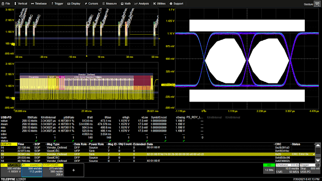
USB-C testing looks at several classes of signals. The main line signal paths—TX1, TX2, RX1, RX2—are high-speed serial data buses each running at 10 or 20 Gb/s. The USB-PD and DPAUX signals operate at much lower speeds. Teledyne LeCroy’s USB-PD Trigger, Decode, Measure/Graph and Physical Layer Tests option (TDMP) is an oscilloscope software package that enables you to trigger on USB-PD signals and decode their content. The decode function interprets the bi-phase mark coding used on the CC lines. It allows time correlation with the other USB-C protocols, as well as physical-layer measurements and eye diagrams (Figure 2).
 |
| Figure 2: USB-PD TDMP can trigger on USB-PD messages for time correlation with DPAUX events. |
Similarly, the DPAUX Decode, Measure/Graph and Physical Layer Tests option acquires, decodes and measures the Alt-Mode sideband signals SBU1 and SBU2. Using either native or I2C transactions, it can decode DPAUX read and write operations as well as characterize the physical layer using eye diagrams (Figure 3).
 |
| Figure 3: DPAUX DMP generates eye diagrams and performs physical layer measurements on DPAUX signals. |
Watch the software at work in our on-demand webinar, "DisplayPort 2.0 Compliance Test Overview, Pt. 2, PHY Testing."
See Also:
Testing DisplayPort 2.0 vs. USB4 Over USB Type-C Connectors
DisplayPort 2.0 Physical Layer Testing
TDME Primer: Automated Timing Measurements

No comments:
Post a Comment