S-parameters describe the electrical properties of electronic interconnects, which can include connectors, printed circuit traces and vias, cables, and oscilloscope probes. Given that instruments such as Teledyne LeCroy’s WavePulser 40iX make measuring S-parameters relatively simple, there are still some aspects of S-parameters that can cause confusion, especially to new users. Here are six things you can do to avoid confusion when working with S-parameters.
1. Know where the fixture ends and the DUT begins
Wherever you want the interface to be, make sure it is in a region of uniform transmission line so that the signal in this region is traveling as a transverse electromagnetic wave (TEM). This will guarantee a clean and reproducible interface that allows separation of the DUT from the system measurement.
Once you define what is the DUT and what are the fixtures, you may need a method to de-embed what you call the DUT from the rest of the measurement system. The topic of de-embedding will be covered in a future blog post.
When a WavePulser 40iX goes through self-calibration, it removes the electrical properties of the internal signal path, moving the measurement reference point to the front of the instrument. The S-parameters for the external cables are known, and the cables are de-embedded so that the measurement reference plane moves right to the end of the cables. That's where the WavePulser effectively ends.
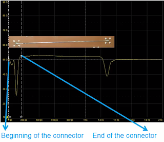
Between the coaxial connectors on the cable and the specific ends of your DUT is a fixture that acts as a geometry transformer. Do you want any of the fixture to be part of your DUT?
A TDR measurement of the composite fixture-DUT-fixture system can sometimes help identify all the interfaces. An example is shown in Figure 1. Do you want your DUT to be just the trace on the board or also the SMA connector and its launch?
Using this criterion, the boundaries between the DUT and the connectors can be isolated. We can now characterize the connectors and adequately de-embedded them, so we've moved the reference plane to the actual beginning of the DUT.
2. Understand S-parameter formalism
 |
| Figure 2. Don’t be confused by the formal definitions used in S-parameters. Each S-parameter element uses the coming out port as the first index number, followed by the going in port index number. |
The device in Figure 2 has four ports. Inputs can be applied to any of the four, and for any input there are four possible outputs, meaning that there are sixteen combinations in total. The formal definitions of S-parameter use index numbers to keep track of the ratios of these signals coming and going, which are attached as subscripts to the letter “S”.
Unfortunately, the second confusing thing about S-parameters is that the index labeling scheme is first the output port and second the input port. So, for a signal input at port 1 and output at port 2, the S-parameter is S21, not S12. The signal coming back from port 1 after going in port 1 is S11, and so on. Pay attention to this, because the labeling scheme is the opposite of what you’d expect.
3. Know which port assignment your S-parameters are using
 |
| Figure 3. There are two possible port assignments for this 4-port device, and choosing the wrong one can cause you to mistake which S-parameters you are viewing. |
Unfortunately, there is no industry consensus as to which of these two approaches should be used. That's why it is so important to always be aware of what the port assignments are in the S-parameters you are using.
The advantage of Case 1 (in Figure 3) is that it makes the insertion loss S21, which is the S-parameter commonly used to describe insertion loss. One of the nice features in the WavePulser 40iX is the ability to reassign ports, so that S-parameters you measure or import can be reconfigured however you want.
We’ll discuss the next three tips in our next blog post, Reading S-Parameters Like a Book, Part II.
For a more in-depth and up-to-date treatment of this topic, watch Dr. Eric Bogatin's webinar series on High-speed Interconnect Characterization.

No comments:
Post a Comment