 |
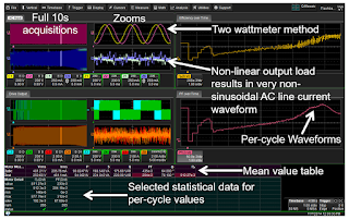
| Figure 1: Screen capture of a 10-s acquisition of AC input and PWM output of a 480-V motor drive |
We took a 10-second acquisition with the MDA set to 1 s/div. The sampling rate is 5 Msamples/s, so we'll need 50 Mpoints of acquisition memory for this long acquisition and many measurements.
The waveforms on the left side of the image are the full 10-s acquisitions. The column to the right of those are zoom traces.
We used a two-wattmeter method for probing the sinusoidal input voltage. Thus, the top display grid in the Zooms column shows only two voltage traces for line-to-line voltages. As noted in our last post, we don't need the third line-to-line voltages to make the calculations.
The next grid down in the Zooms column is the AC line current. By definition, any inverter is a non-linear load to the AC input. That's why probing the input gives us an AC waveform that looks nothing like a sine wave. What comes out of the wall is an AC sinusoid, but that doesn't guarantee that it will stay that way with a load connected to it. We must be careful to use proper techniques to measure power. Failure to do so can get you in a lot of trouble.
At center left in the image are the full line-to-line voltage acquisitions of two of the lines on the drive's PWM output. Those traces are overlaid on each other in green. Below that, in orange, are the current waveforms. The zoom trace to the right of the current traces shows a large amount of noise, which is what one would expect for a 480-V line. There's a lot of switching going on that creates noise that, in general, is damped by the motor winding. These high-frequency transients and noise have little effect, if any, on the wattage measurements on the motor.
The table at bottom left shows calculated RMS currents and voltages. The input is at 481 V RMS. Because it's a variable-frequency drive, the output operates on a little more than half of the input voltage. You can also see the current draws from the utility supply and from the drive output.
To the right of those per-cycle statistical values are the mean values for power. The power factor seems low but these are full-spectrum calculations. If we'd filtered for only the fundamental, the power factor would probably have been around 0.95.
The two display grids to the right of the screen capture are plots of efficiency over time (top) and PF over time (bottom). We started up the drive and then applied a load. Note how the PF starts very high, drops off, recovers somewhat, and then drops off again with the application of the load. As the load increases, the PF gradually ramps up until we shut off the drive.
With power measurements of both input and output, we can plot efficiency over time. This plot closely parallels that of PF over time. The mean value for efficiency on the entire 10-s waveform is about 50%, but the plot shows that it goes much higher and much lower depending on the load.
From this overview of three-phase power measurements on the Motor Drive Analyzer, one can see the wealth of information that can be garnered from a single acquisition.
Previous posts in this series:
Back to Basics: The Fundamentals of Power
Back to Basics: Fundamentals of AC Line Power (Part II)
Back to Basics: Three-Phase Sinusoidal Voltages
More Basics of Three-Phase Sinusoidal Voltages
Back to Basics: AC Sinusoidal Line Current
Power Calculations for Pure Sine Waves
Power Calculations for Distorted Sine Waves
Three-Phase Power Calculations
No comments:
Post a Comment