 |
| Figure 1: A single-phase AC current vector rotates at 50 or 60 Hz |
When we're talking about AC sinusoidal current, we are always talking unit values of IRMS but most often, we'll see it stated as IAC. These terms are used interchangeably in documentation and technical literature, though. If flowing through a single conductor, line current has a single phase, and if flowing in three conductors, it has three phases.
In terms of measurement reference points for line current, in a Wye (Y) system, all line current flows to neutral, so line currents are winding currents. In a Delta (Δ) system, line currents are terminal currents that flow into two different windings.
Line current is nominally a sine wave, but in the real world, it never appears as a pure sine wave. It always contains some amount of distortion that standards typically limit to <5%.
As with voltage, a single-phase current vector rotates at a given frequency (typically 50 or 60 Hz; Figure 1). At any given moment in time, the current's magnitude is expressed by:
I * sin (α)
 |
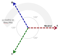
| Figure 2: Three-phase AC current has three rotating current vectors |
When you move to three-phase line current, you're looking at not one but three different line-current vectors that rotate at, again, usually 50 or 60 Hz. As with voltage, the time-varying "rotating" current vectors appear as three sinusoidal waveforms. These three vectors are separated in phase by 120° and are of equal peak amplitude for a balanced load. At any given time, the current's magnitude can found using:
IX * sin (α)
where IX = magnitude of line-current vector and (α) = angle of rotation (in radians).
 |
| Figure 3: Current probes and transducers perform high-accuracy measurements |
There also are specialty current transducers available such as those from Danisense. Like the current probes, these devices also are very accurate and span a frequency range from DC to about 100 kHz.
If you don't need a device that measures down to DC, you have other options as well. Rogowski coils have a frequency response that depends on the specific model, but they typically range down to 5-15 Hz. These split-core devices run the gamut in loop sizes from very small to very large.
Pearson current transformers also have varying frequency response but typically measure down to 5 Hz. They are also mostly split-core devices that have built-in shunt resistors for scaled voltage output. Lastly, conventional turns ratio current transformers typically cover the line frequency range with a little margin. These also have a scaled output current, but need a shunt resistor on the output to convert to voltage output. Be aware that dangerous open-circuit voltages can appear at the output of these devices: Use them with extreme caution and avoid open-circuit operation.
Teledyne LeCroy offers a current sensor adapter for its oscilloscopes that does the hard work of interfacing third-party current sensors to the oscilloscopes and allows them to operate much as a probe would. They're programmable, customizable devices that convert any linear voltage or current input to an output scaled in Amperes. Unless you really enjoy fiddling around with current sensors, these adapters greatly simplify the setup process.
We'll continue in a subsequent post with some power calculations for pure sine waves.
Previous posts in this series:
Back to Basics: The Fundamentals of Power
Back to Basics: Fundamentals of AC Line Power (Part II)
Back to Basics: Three-Phase Sinusoidal Voltages
More Basics of Three-Phase Sinusoidal Voltages
No comments:
Post a Comment