One of the most basic things to know when using any probe is “what is the maximum voltage the device can safely measure?” The answer isn’t as straightforward as you might imagine, it requires understanding several key probe specifications as well as the nature of your signal.
Single-ended Range
 |
| Figure 1. Single-ended range is measured voltage input to ground. |
Dynamic Range and Maximum Non-destruct Input Voltage
 |
| Figure 2. Differential mode range is measured between inputs. |
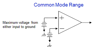
Differential range (DMR) is the maximum instantaneous voltage that can safely appear between the two inputs of a differential amplifier, shown in Figure 2. You don't need a ground or a board reference connection. It's very easy to do, but pay attention to the common mode range (CMR) of the probe to make sure you don't exceed it, either. Each one of those plus and minus inputs has a maximum input voltage compared to ground that it's rated for, as well, as shown in Figure 3. As we discussed in an earlier post on dynamic ranges, the common-mode range is not always symmetrical with respect to ground, which means that in some amplifiers, the common-mode range in the positive direction from ground will be different from that in the negative direction.
 |
| Figure 3. Common mode range is measured either input to ground. |
In the high-voltage probe world, we know that CMR (and the source impedance of the load) dictates the Measurement Category (CAT) rating, and it's typically at 1000 V but could be higher or lower. CMR is not normally directly measured by the probe (as is DMR), but is achieved through the probe’s topology. It’s important to be sure your probe has a suitable common mode range for the circuit you're going to be connected to.
Any conventional high-attenuation, high-voltage differential probe commonly has a specification that indicates the maximum common mode voltage at which the probe can be used to ensure operator safety and equipment safety. This is often referred to as the maximum non-destruct input voltage. It does not mean that the probe will give you a good measurement result at that voltage; it just means you won't be killed, your equipment won't be damaged, and your DUT won't be destroyed.
Voltage Swing
Understanding what your actual common mode voltage requirements are involves understanding the voltage swing of the signal you’re probing. Take for example a gate drive. The gate drive is a low voltage signal, but on the upper side of a bridge, it's floating at the DC bus voltage potential. If the DC bus voltage is 500 V and the gate voltage is 10 V, then the gate voltage is swinging from 500 to 510 V, and you need to have isolation for the 500 V. This is an increasingly important specification for those working in power conversion, because things like grid type solar PV inverters and UPS systems that don't connect directly to an AC line can typically run on 1500 Vdc and higher.
As we think about voltage dynamic range, the concept of voltage swing is where some people experience confusion. An AC sinusoid input, such as a wall socket rated to 120 Vrms, has a peak and a peak-to-peak. That means it swings from 0 to plus 170 Vpeak, then it goes to minus 170 Vpeak, which is 340 V peak-to-peak. There is never a case in which the signal pauses at zero volts. So, it's actually a much wider range to be measured, even though the socket is rated 120 Vrms.
If we look at an inverter or drive output line-to-line PWM output, we see a series of pulses going from zero volts (board referenced) to high DC bus voltage. In this case, the signal pauses at zero volts before going from zero to minus DC bus voltage. So here you might say, "Well, I've got that same peak-to-peak swing." But not really, because in the case of a pulse, you're stopping at zero, you don't go from the plus voltage peak to minus voltage peak in one swing as you do with the AC sinusoid. The range the probe has to measure is only from zero to plus Vpeak or zero to minus Vpeak, so the dynamic voltage range is equivalent to the Vpeak rating. You have to think about the dynamic range for these two kinds of signals very differently.
Learn more about probe design and voltage specifications in our on-demand webinar, Probing in Power Electronics, What to Use and Why: Part I.
Related posts:
No comments:
Post a Comment