 |
| Figure 1: A 2-pole, 1-MHz Butterworth low-pass filter applied to an acquired waveform |
You need to test, we're here to help.
You need to test, we're here to help.
30 December 2014
Filtering Signals with MATLAB
17 December 2014
What S-parameters Reveal About Interconnects (Part III)
 |
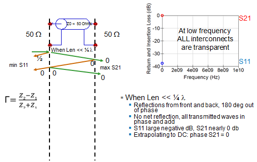
| Figure 1: How ripple is introduced into S11 and S21 |
09 December 2014
What S-parameters Reveal About Interconnects (Part II)
 |
| Figure 1: Measuring S-parameters of a two-port interconnect |
03 December 2014
What S-Parameters Reveal About Interconnects
 |
| Figure 1: S-parameters are derived by applying an incident wave to an interconnect; we can consider this process in either the time or frequency domains |
14 November 2014
An Under-the-Hood View of PCIe 3.0 Link Training (Part I)
 |
| Figure 1: An overview of the elements of PCIe 3.0 dynamic link equalization |
10 November 2014
PCIe 3.0 Dynamic Link EQ: De-Emphasis, Preshoot, Cursors, and Presets
 |
| Figure 1: De-emphasis, a key transmit-side equalization technique for PCIe 3.0, boosts high-frequency content |
06 November 2014
The Hows and Whys of PCIe 3.0 Dynamic Link Equalization
 |
| Figure 1: SI problems are the root cause for dynamic link equalization in PCIe 3.0 |
15 October 2014
DDR Memory Testing Part IV: Preparing for Testing
 |
| Figure 1: For compliance testing, DDR transition density should be as high as possible |
08 October 2014
DDR Memory Testing Part III: What Not to Do
 |
| Figure 1: Damping resistors on solder-in probe tips |
01 October 2014
DDR Memory Testing Part II: Using Interposers
 |
| Figure 1: The anatomy of a chip interposer |
24 September 2014
Eliminate Pitfalls of DDR Memory Testing
 |
| Figure 1: DDR test configuration for a desktop computer |
05 September 2014
Oscilloscope Basics: Using The Display Graticule
 |
| Figure 1: The display graticule, the grid of intersecting lines overlaying the signal display area, is the original oscilloscope measurement tool |
20 August 2014
Go Back to School on Signal Integrity
No matter how much we might think we know about signal integrity, there's always more to learn. The laws of physics never change but we might come across new scenarios in which to apply them. Circuits with higher levels of functionality are constantly being squeezed into smaller, more portable spaces; the closer together we pack active components and transmission lines, the more acute their sensitivity is to electromagnetic energy. Everything's either a transmitter or a receiver in some sense and everything has effects on other components, intended or otherwise.
05 August 2014
Oscilloscope Basics: History Mode
 |
| Figure 1: Initial setup of WaveSurfer 3000 with a 2-MHz pulse waveform fed into Channel 1 |
30 July 2014
Video: WaveSurfer 3000 and the MAUI User Interface
Oscilloscopes are often an engineer's best friend, but that can change depending on how easy or difficult a given instrument is to use. Sure, the oscilloscope's capabilities and technical specs are critical, but if the machine is difficult or non-intuitive to interact with, the user ends up wasting time figuring out what should be simple.
24 July 2014
How Many Channels is Enough?
 |
Figure 1: A switch-mode power supply driving a fixed load
can be designed and optimized specifically for that load.
|
Having said that, there are some applications that by their very nature surpass four channels. Moreover, some of these applications concern circuits and devices that are produced in extremely high volumes. A case in point is switch-mode power supplies, such as those typically found in notebook PCs, tablets, or embedded systems.
18 June 2014
Applying Selective Averaging to Waveform Acquisitions
 |
| Figure 1: Using pass/fail testing to average only those waveforms which are inside the tolerance mask |
09 June 2014
Video: Vertical Controls on the HDO Oscilloscopes
Here's another in our continuing series of tutorial videos. This time, we'll review the use of the vertical controls on a Teledyne LeCroy HDO oscilloscope. These controls facilitate positioning and scaling of waveforms vertically on the oscilloscope's display. Note that although we're demonstrating these controls on an HDO, you'd be rather hard pressed to find an oscilloscope from any manufacturer without a volts/div and vertical offset control. Thus, this video is applicable to whatever oscilloscope you have on your bench.
There are quite a few tutorial videos for a broad range of Teledyne LeCroy products on our YouTube channel. Head on over whenever you need a refresher!
There are quite a few tutorial videos for a broad range of Teledyne LeCroy products on our YouTube channel. Head on over whenever you need a refresher!
22 May 2014
The Effects of Passive Probe Ground Leads
 |
| Figure 1: Teledyne LeCroy's PP108, a representative passive probe |
15 May 2014
Back to Basics: S-parameters
 |
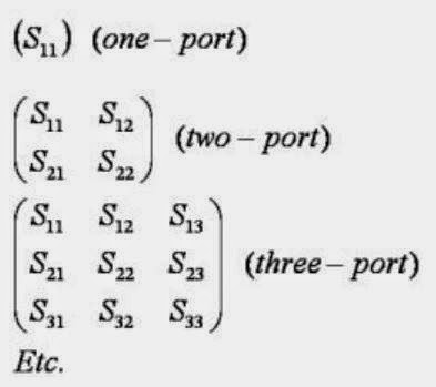
| Figure 1: S-matrices for one-, two-, and three-port RF networks |
16 April 2014
Is Your Testbench Mixed-Signal Ready?
 |
| Figure 1: A representative block diagram of a mixed-signal embedded system |
09 April 2014
Applying Multi-Stage, Multi-Rate Digital Filtering
 |
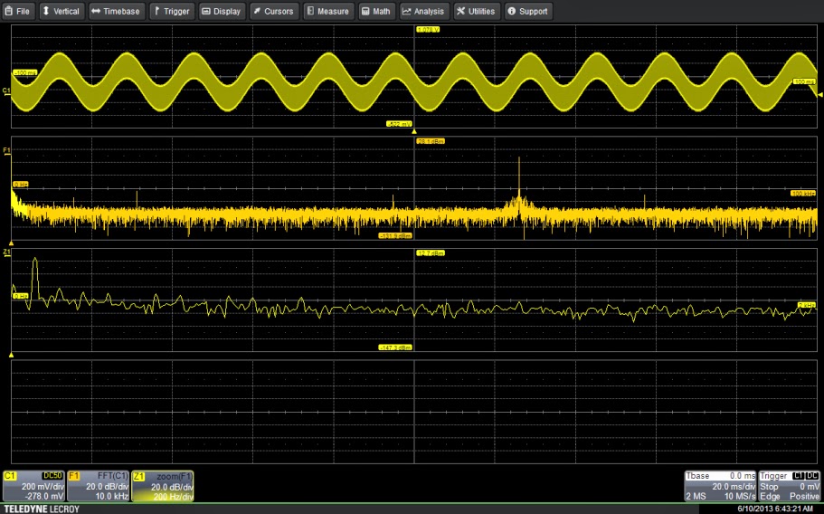
| Figure 1: The input signal shows both the desired 63-kHz signal along with a 60-Hz component. Zoom trace Z1 shows the 60-Hz component in detail. |
02 April 2014
Understanding Probe Calibration Methods (Part II)
 |
| Figure 1: Experimental setup for comparing a source-referred signal to an unloaded signal |
26 March 2014
Using Digital Filters
 |
| Figure 1: Using a band stop filter to remove a 5-MHz sine wave from a 4-MHz square wave |
19 March 2014
Tips and Tricks: Rescaling for Non-Voltage Measurements
 |
| Figure 1: Using math rescale to read a current probe's output directly in Amperes |
12 March 2014
Use Trend Functions To Take Power's Pulse
When troubleshooting or debugging almost anything, the first step is usually to check what's going into the device or circuit and what's coming out on the other side. So it is with power supplies, which leads us to power line monitoring and trend functions.
05 March 2014
Measuring Time-Interval Error in Serial Data Waveforms
 |
| Figure 1: The first step in quantifying jitter is to determine measured times of arrival for bit transitions |
26 February 2014
Understanding Probe Calibration Methods
If there's a topic concerning probes that causes confusion, questions, and misunderstandings, it's loading. It would be a much simpler world if attaching a probe to a circuit under test had no effect on either the signal being measured or the device the probe is connected to. Unfortunately, the world isn't quite so simple.
19 February 2014
Making Sense of Probe Terminology
As oscilloscope users, we know that the probe is a critical element in getting signals from the device under test into the instrument. The ideal probe would have perfectly flat magnitude response and perfectly linear phase response across its entire frequency range. Unfortunately, that probe, though striven for by all oscilloscope manufacturers, does not exist.
05 February 2014
Why Should You Measure Jitter?
 |
| Figure 1: Designing a serial-data channel with first-pass success means analysis and mitigation of jitter sources |
29 January 2014
Tips and Tricks: Stabilizing a Waveform Trace
22 January 2014
The Components of Total Jitter
 |
| Figure 1: An overview of the jitter hierarchy, or "jitter tree," showing the various elements that make up total jitter |
16 January 2014
Mr. Oscilloscope, Meet Mr. Computer
 |
| Figure 1: WaveStation software enables full remote control of an oscilloscope from a Windows PC |
08 January 2014
Let's Get Serial: About Manchester Data Encoding
 |
| Figure 1: An example of Manchester coding |
Subscribe to:
Comments (Atom)
