 |
| Figure 1: AC line voltage is a single-phase vector that rotates at a given frequency |
You need to test, we're here to help.
You need to test, we're here to help.
08 December 2016
Back to Basics: Fundamentals of AC Line Power (Part II)
18 November 2016
Back to Basics: The Fundamentals of Power
30 September 2016
Dynamic Range, Signal Integrity, and ESD Pulses
 |
| Figure 1: Use your oscilloscope's full vertical range to take full advantage of the ADC's resolution |
28 September 2016
How Does Sampling Rate Affect ESD Pulse Measurements?
 |
| Figure 1: Characterization of an ESD pulse's rise time depends largely on the oscilloscope's sampling rate |
13 September 2016
Why IEEE's Pulse Definitions and ESD Pulses Don't Mix
 |
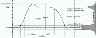
| Figure 1: The IEEE's pulse definitions, which don't fit the bill for measuring ESD pulses |
30 August 2016
Making EMC/ESD Pulse Measurements
 |
| Figure 1: Oscilloscopes are used for testing in the green-shaded boxes |
15 July 2016
Are You Ready for Bluetooth 5?
The Bluetooth Special Interest Group, which is the body that oversees the protocol's specification, doesn't stand still but rather continues to develop and improve Bluetooth technology. With an eye toward building an accessible and interoperable Internet of Things (IoT), the next version of the Bluetooth specification—Bluetooth 5—is slated to appear by early in 2017 and as soon as this fall.
08 July 2016
The Power Delivery 2.0 Protocol in Action
 |
| Figure 1: A high-level view of a PD 2.0 power contract negotiation |
14 June 2016
Just the FAQs: Waveform Averaging
 |
| Figure 1: The upper grid displays raw samples directly from the ADC; the lower grid displays the average of 1000 acquisitions. |
02 June 2016
USB Type-C and Dual-Role Port Devices
 |
| Figure 1: This protocol analyzer capture shows how a DRP alternates between voltage source and sink until it sees one or the other at the far end of a link |
19 May 2016
USB Type-C and Power Delivery Messaging
 |
| Figure 1: Power Delivery messaging comprises two types: Control and Data |
13 May 2016
The Evolving User Interface: Cursors, Triggers, and More
 |
| Figure 1: Need to reposition a cursor? Touch, hold, and drag it |
26 April 2016
The Evolving User Interface: Add New
 |
| Figure 1: Dragging a channel, memory, math, or zoom trace to the Add New box creates a new trace of the same type |
18 April 2016
The Evolving User Interface: Changing Sources
 |
| Figure 1: Changing the source of a trace is as simple as a drag-and-drop of the desired source's descriptor box onto the target descriptor box |
05 April 2016
The Evolving Oscilloscope User Interface
 |
| Figure 1: MAUI is Teledyne LeCroy's intuitive touch-based user interface |
17 March 2016
The Challenges of GFCI Measurements
 |
| Figure 1: An example of a GFCI |
04 March 2016
Performance Considerations For Optical Modulation Analysis
 |
| Figure 1: Error-vector magnitude defined |
01 March 2016
What Is An Optical Modulation Analyzer?
 |
| Figure 1: A representative block diagram of a coherent transmitter and receiver |
18 February 2016
The Fundamentals of Coherent Signals
 |
| Figure 1: These two coherent light waves have a constant phase offset |
01 February 2016
USB Type-C Cable Detection
 |
| Figure 1: The four possible states of connection for a USB Type-C cable |
05 January 2016
A Look at USB Type-C and Power Delivery
 |
| Figure 1: The USB Type-C connector alongside its Micro-B counterpart |
Subscribe to:
Comments (Atom)

