 |
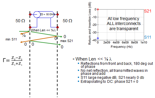
| Figure 1: How ripple is introduced into S11 and S21 |
Here's what we mean when we say patterns: In almost every return-loss (S11) measurement there will be some ripple (and sometimes in the insertion loss, or S21, as well). The ripple is the result of reflections. In insertion-loss measurements, there is typically a monotonic dropoff; higher frequencies result in more loss. Often, we'll see broad dips in the insertion loss due to 1/4-λ stub resonance, and sharper dips resulting from coupling to a cavity or to floating metal in the circuit.
First, let's look at the ripple in S11 (Figure 1). Imagine an interconnect, with 50-Ω impedances on both ports, through which we'll send a waveform. However, the interconnect itself, which is much less than 1/4-λ in length, presents an impedance of 30 Ω, resulting in a reflection. Using the formula to calculate the reflection coefficient shown at the bottom left of Figure 1, we arrive at a negative number, which indicates that the impedance bump causes a 180° phase change.
However, some of the waveform transmits through the interconnect. Due to the interconnect's very short length, there is no phase change on the transmitted portion. The wave does, however, see an impedance bump from 30 Ω to 50 Ω, so there is yet another reflection.
But this time, Z2 = 50 Ω and Z1 = 30 Ω, which yields a positive number in the reflection coefficient calculation. Thus there is no phase shift off of this reflection. After a few ping-pong cycles, adding up the reflected and incident signals yields a minimum for S11 and a maximum for S21. A plot shows us that there is no loss at very low frequencies in any interconnect, so S21 is 0 dB. There is no signal reflected, so S11 is some very large negative value. At low frequency, all interconnects are transparent, which is something that we all intuitively know about low-speed signals and circuits. When the length of the channel is much less than one-quarter of the signal wavelength, the reflections from the front and back are 180° out of phase and they subtract. We get a minimum. There’s no net reflection, all the transmitted waves add together, and we get a maximum at S21.
 |
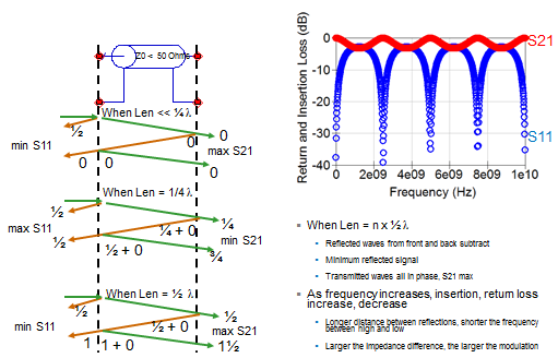
| Figure 2: What happens when an interconnect's length is one-quarter of the signal's wavelength? |
Another important factor is the length of the socket and the associated time delay. What is the speed of a signal through a material? A good rule of thumb is roughly 6 inches per nanosecond. The time delay is the length divided by the speed.
What if the length of the interconnect is equal to 1/4 λ? Again, referring now to Figure 2, the incident signal sees a 50-Ω impedance at the ports and a 30-Ω impedance on the interconnect itself, and there is a 180° phase shift on the reflection. The signal that transmits through, however, undergoes a 1/4-λ phase shift due to the interconnect's length. Another reflection occurs with zero phase shift, but we add that 1/4-λ phase shift for the trip through the interconnect. Another 1/4-λ phase shift is added for the next reflection, giving us 1/2-λ phase shift, and yet another 1/4-λ phase shift is added on a final reflection for a total of 3/4-λ phase shift. The end result is a maximum for S11 and a minimum for S21. This configuration is true whenever the interconnect length is 0.5X some integer plus 1/4 λ.
 |
| Figure 3: Ripple resulting from multiple reflections |
Now, let's consider the case where the interconnect is 1/2 λ in length (Figure 3). The incident waveform is phase-shifted by half a wavelength as it transmits through the interconnect, again due to the length. The first reflection has no phase shift (plus the 1/2-λ phase shift on transmit). Subsequent reflections result in a waveform that is 1-1/2 λ out of phase, which means a minimum for S11 and a maximum for S21. Continuing in this pattern in multiple integers produces the ripple seen in the plot at top right of Figure 3. Remember that if the return loss is more than -10 to -13 dB, it will have an impact on the insertion loss. That will carry over into ripple on S21.
In conclusion, there are interesting things that can be gained by looking at ripple. The longer the interconnect is, the shorter of the frequency between the high and low, and the closer together the ripples will be. For a very long interconnect, the ripples will be closely packed. Conversely, in a very short interconnect, the ripples will be spaced far apart. And, the larger the impedance difference between the ports and the interconnect itself, the larger the modulation will be in a ripple waveform.
No comments:
Post a Comment