 |
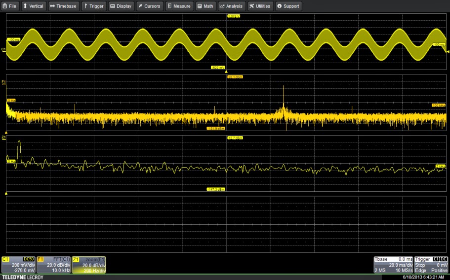
| Figure 1: The input signal shows both the desired 63-kHz signal along with a 60-Hz component. Zoom trace Z1 shows the 60-Hz component in detail. |
With Teledyne LeCroy's Digital Filter Package (DFP2), users can select any of seven standard filter types or define a custom filter for application to measured data. You can specify a range of pass-band limits and transition (roll-off) widths for any filter, which are implemented as digital finite impulse response (FIR) filters. The range of band-edge frequencies is a function of the oscilloscope's effective sampling rate. Using the available math traces on Teledyne LeCroy oscilloscopes, you can implement multi-stage, multi-rate filters to extend the range of the DFP2 package's filter limits.
Let's see how this works with an example of a signal (Figure 1). This is a signal you'll commonly find in switching power-supply measurements. The measured waveform contains a 63-kHz pulse-width-modulated signal riding on top of a 60-Hz sine wave. Removal of the 60-Hz signal requires a high-pass filter with a pass-band edge above 60 Hz.
 |
| Figure 2: Shown is the series of math operations used to implement a multi-stage, multi-rate digital filter |
Reducing the sampling rate increases the possibility of aliasing the data, especially with a harmonic-rich signal like this one. To limit the possibility of aliasing, the data can be sampled at a high rate and then low-pass filtered, using a digital filter, before decimation. This combination of filtering and decimation before performing another filtering operation on the data is called "multi-stage, multi-rate" digital filtering. It allows you to reduce the effective sampling rate with minimal risk of aliasing, thus extending the usable range of the DFP2 filters.
So here's the multi-stage, multi-rate implementation (Figure 2). The upper trace is the acquired waveform sampled at 10 Msamples/s. The goal is to reduce that sampling rate by 10:1. We accomplished this by first low-pass-filtering the acquired data with a bandwidth of less than 50% of the desired effective sampling rate of 1 Msamples/s.
Math trace F4 is the setup for the high-pass filter. The cutoff frequency is 200 Hz with a transition zone width of 50 Hz. Note that the 60-Hz component has been greatly reduced by the filtering process.
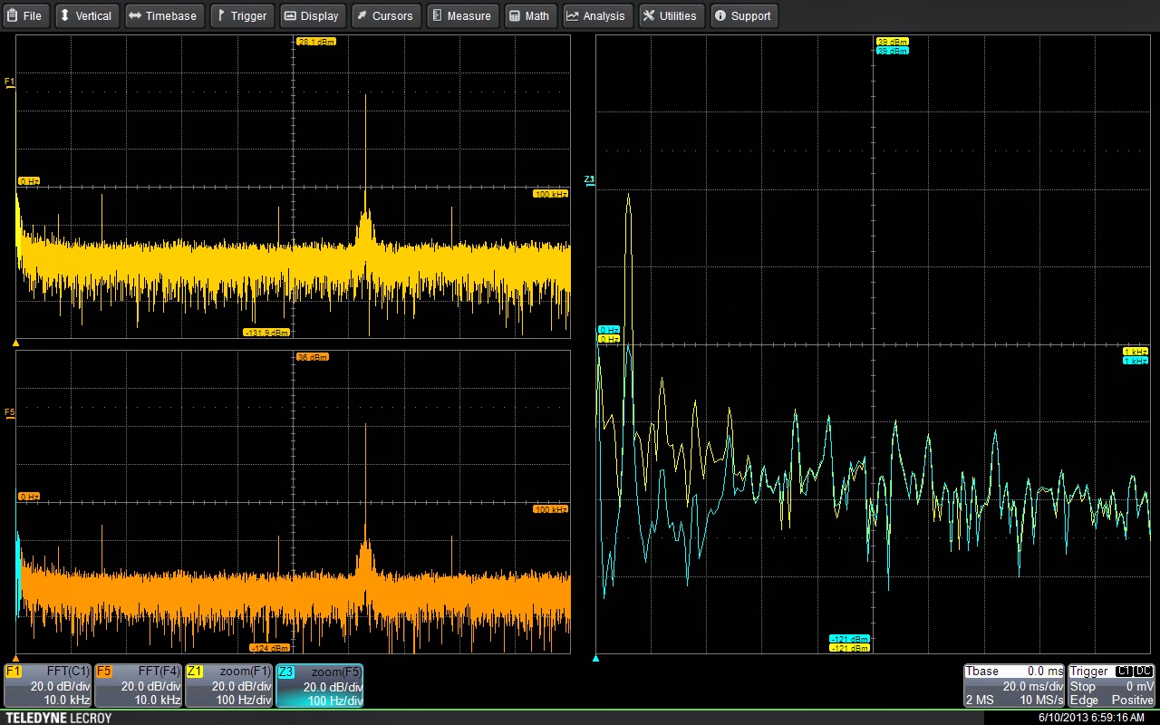
In Figure 3, a comparison of the input and output frequency spectra shows that the 60-Hz component has been reduced by 40 dB. This can be seen in the right-hand zoom trace comparison. The high-pass filtering does not affect spectral components above 300 Hz.
With this example, we can see how multi-stage, multi-rate filtering extends the usable range of the DFP2 digital filters.

No comments:
Post a Comment