You need to test, we're here to help.

You need to test, we're here to help.

08 October 2019

Basics of Power Conversion: Power Semiconductors

The basic building blocks of power conversion circuits are the power MOSFET and the IGBT
Figure 1: The basic building blocks of power
conversion circuits are the power MOSFET and
the IGBT; shown are (left) an N-channel
enhancement-mode MOSFET and (right)
a P-channel (minority carrier) IGBT
There are a multitude of circumstances that make power conversion a necessity. Power conversion, of course, is the converting of electric power from one form to another, from one voltage to another, or one frequency to another; it also encompasses any/all combinations of these.

03 May 2019

A Real-World FFT Example

Figure 1: Shown at top right is the output of a 5V switch-mode power supply acquired with an RP4030 active voltage-rail probe
Figure 1: Shown at top right is the output of a
5V switch-mode power supply acquired
with an RP4030 active voltage-rail probe
Performing a fast Fourier transfer (FFT) on an oscilloscope can be likened to driving a car. Just as there are two dominant strains of power-train transmissions, there are two dominant approaches to transferring signals acquired on an oscilloscope from the time domain to the frequency domain. There's the stickshift approach, in which the FFT parameters are set manually, and the automatic approach, in which you let the oscilloscope make decisions for you.

08 April 2019

Fast Fourier Transforms: Automatic Edition

Figure 1: Shown is the user interface for Teledyne LeCroy's Spectrum Analyzer software option
Figure 1: Shown is the user interface for Teledyne LeCroy's
Spectrum Analyzer software option
Many motorists love the experience of driving a sporty car with its convertible top down and a stickshift manual transmission. Others don't want the hassle of a clutch and prefer the user-friendly feel of a slick automatic that does some of the work for them. Oscilloscopes can provide the same sort of choice for many measurement tasks in the same instrument.

02 April 2019

Fast Fourier Transforms: Stickshift Edition

Figure 1: Shown at left is a 50-kHz input sine wave with the FFT of the same signal at right
Figure 1: Shown at left is a 50-kHz input sine wave
with the FFT of the same signal at right
Perhaps you're old enough to remember when more cars had stickshifts. They're a little bit more work to drive than cars with automatic transmissions, but the experience can be much more rewarding. Oscilloscopes these days are like cars with both types of transmissions, and you can use either one for many tasks. One of those tasks is fast Fourier transforms (FFTs), and in this post we'll take you through driving an oscilloscope to perform an FFT with a stickshift.

25 March 2019

The Resolution Revolution In Oscilloscopes

Figure 1: Teledyne LeCroy's WavePro HD exemplifies today's high-resolution, high-bandwidth instruments
Figure 1: Teledyne LeCroy's WavePro HD exemplifies
today's high-resolution, high-bandwidth instruments
Oscilloscopes have been around for a very long time now, and older oscilloscope users will remember the heyday of those analog boat anchors of the '60s and '70s. Many have survived and are still usable if you don't need much bandwidth (and have the means to calibrate them if necessary). I used to scout local hamfests looking for bargains on them. Many techs and engineers cut their teeth on those behemoths. You could learn a lot about design if you poked around inside them, too.

08 March 2019

Which Windowing Function to Use in FFTs?

Figure 1: Examples of a Hamming function (blue) and Hanning function (red)
Figure 1: Examples of a Hamming
function (blue) and Hanning function
(red)
When performing a fast Fourier transform on an acquired waveform, you'll often encounter situations where the waveform doesn't sit neatly within the oscilloscope's acquisition window so that the voltage is the same at the window's beginning and end. The ensuing discontinuity from window to window results in high-frequency artifacts, and the way to address this issue is a technique known as "windowing."

27 February 2019

About Windowing in Fast Fourier Transforms
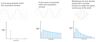
Windowing a waveform that's not periodic within the acquisition window reduces spectral leakage
Figure 1: Windowing a waveform that's not periodic within
the acquisition window reduces spectral leakage
The second artifact in FFT calculations is more serious and is also the source of some confusion. A good source for information on this topic of windowing is an application note published by National Instruments.

22 February 2019

About Data Truncation in Fast Fourier Transforms

The first precondition of using the Fourier transform is a repetitive signal
Figure 1: The first precondition of using the Fourier transform
is a repetitive signal
Our last post discussed how time-domain signals acquired by an oscilloscope might be translated into the frequency domain using the discrete Fourier transform. We noted that using the Fourier transform only works if our signal is repetitive (Figure 1), and that it allows us to identify only harmonics of the first harmonic frequency, which is 1/acquisition window. Moreover, the discrete Fourier transform, if used on a large number of data points, is relatively slow to calculate.

30 January 2019

Getting From the Time Domain to the Frequency Domain

A fundamental underlying assumption of a discrete Fourier transform is a repetitive waveform
Figure 1: A fundamental underlying assumption of a discrete
Fourier transform is a repetitive waveform
Fundamentally, oscilloscopes are time-domain instruments: We use them to acquire signals from our circuitry or device under test, and the instrument displays them in the time domain. We see the voltage of the signal in the vertical axis, and we see how that voltage changes over time in the horizontal axis.