You need to test, we're here to help.

You need to test, we're here to help.

27 February 2018

Transmission Lines (Part IV): More Essential Principles

The return current in a transmission line is as important as the signal current
Figure 1: The return current in a transmission line
is as important as the signal current
In our continuing survey of the topic of transmission lines, we'd begun in our last post to cover some essential principles that govern their behavior. We're not quite done with those, so in this post we'll discuss more principles that should be part of the foundation of how you think about interconnects.

26 February 2018

Transmission Lines (Part III): Essential Principles

All interconnects are transmission lines with a signal path and a return path (not ground)
Figure 1: All interconnects are transmission lines with a signal
path and a return path (not ground)
Now that we've covered some of the principles and assumptions that underlie transmission lines in two prior posts, we can now directly address the topic with some essential principles that you need to understand.

23 February 2018

Transmission Lines (Part II): More on Bandwidth vs. Rise Time

In the frequency domain (right), a near-ideal square wave displays predictable 1/f amplitude dropoff
Figure 1: In the frequency domain (right), a near-ideal
square wave displays predictable 1/f amplitude dropoff
We began this series about transmission lines by thinking about some pertinent principles and relationships that can help form our thinking about the topic. In particular, we'd covered the relationship between bandwidth and rise time and why we have this rule of thumb that says that bandwidth can be estimated using 0.35/10-90% rise time.

20 February 2018

Transmission Lines (Part I): Introduction

All oscilloscopes have a Cal output like the one pictured here
Figure 1: All oscilloscopes
have a Cal output like the
one pictured here
Somewhere on the front panel of almost any oscilloscope is a "Cal" reference signal output (Figure 1). That signal is really intended for adjusting the capacitance compensation screw to calibrate a 10X high-impedance probe, but most of us know it simply as the Cal signal. Have you ever noticed that the Cal signal's rise time seems to be highly dependent on the length of the cable attached to it, and maybe even wondered why?

16 February 2018

Probing Techniques and Tradeoffs (Part XI): Non-Ideal Situations

VP@Rcvr builds a transmission-line model to virtually move less-than-ideal probing points
Figure 1: VP@Rcvr builds a transmission-line model
to virtually move less-than-ideal probing points
In using an oscilloscope to investigate transmission-line performance, we often encounter situations in which we don't have the luxury of probing at the ideal location. Fortunately, there are software tools that enable us to virtually move our probing point close to the receiver.

12 February 2018

Probing Techniques and Tradeoffs (Part X): More Best Practices
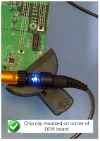
Chip clips; they're not just for snacks anymore
Figure 1: Chip clips;
they're not just for
snacks anymore
In probing circuits, as with most endeavors, there are some best practices you can use to enhance your chances of obtaining optimal measurements. We began exploring this concept in our last post, and we'll continue here with more best practices.

09 February 2018

Probing Techniques and Tradeoffs (Part IX): Best Practices

The typical manner of using a hands-free probe holder can cause issues
Figure 1: The typical manner
of using a hands-free probe
holder can cause issues
Having covered many of the theoretical aspects of probing signals, it's now useful to cover some best practices for high-speed active probing. We'll use some examples involving probing of DDR memory to illustrate what works best and what might not be a good idea from a practical standpoint.

08 February 2018

Probing Techniques and Tradeoffs (Part VIII): Gain/Attenuation vs. Noise

Noise comparison of a Teledyne LeCroy D1605 probe and a competing model
Figure 1: Noise comparison of a
Teledyne LeCroy D1605 probe and
a competing model
When discussing oscilloscope probes and dynamic range as we've been doing of late, we must also touch upon the associated topics of internal gain/attenuation and how that relates to noise.

06 February 2018

Probing Techniques and Tradeoffs (Part VII): More on Dynamic Range

Input offset range is how much differential offset a probe can apply to an input signal to bring it within its differential-mode output range
Figure 1: Input offset range is how much
differential offset a probe can apply to
an input signal to bring it within its
differential-mode output range
In our last post in this series, we'd begun discussing the third of three types of dynamic range as applied to probes, and that is input offset range. This is the maximum differential offset that a probe can apply to the input signal to bring it within the probe's differential-mode dynamic range.

05 February 2018

Getting The Most Out Of Your Oscilloscope: Physical-Layer Tools

Trigger dialog boxes will match the protocol of interest
Figure 1: Trigger dialog boxes will
match the protocol of interest
Debugging and validation of the physical layer of serial-data links is a preeminent oscilloscope application area these days. Today's real-time digital oscilloscopes have a wealth of tools to help you dig into any/all serial protocols and learn what's really going on electrically with your serial links.

02 February 2018

Getting The Most Out Of Your Oscilloscope: Math Functions
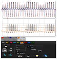
Parameter math functions provide a way to create custom parameters
Figure 1: Parameter math functions
provide a way to create custom
parameters
Parameter math functions are an important part of an oscilloscope's analysis capabilities. Using parameter math, you can create custom parameters based on simple arithmetic relationships between existing parameters. It allows you to add, subtract, multiply, divide, or rescale parameters (Figure 1).

01 February 2018

Getting The Most Out Of Your Oscilloscope: Sequence and History Modes

Sequence mode grabs rare triggered events from long captures and stores them in segments
Figure 1: Sequence mode grabs rare triggered events from
long captures and stores them in segments
When using an oscilloscope, there are bound to be instances in which you need to capture a large number of fast pulses in quick succession, or, conversely, a small number of events separated by long periods of time. Both are challenging for typical signal acquisition modes. But many Teledyne LeCroy oscilloscopes provide what's known as Sequence mode, which lets you capture these events while ignoring the long intervals between them.

Getting The Most Out Of Your Oscilloscope: WaveScan and XDEV Custom Parameters

Using WaveScan to search for rare glitch events
Figure 1: Using WaveScan to search
for rare glitch events
In earlier posts about how to maximize your oscilloscope's utility, we've discussed how to properly capture a waveform, making measurements, and extracting more meaningful information from those measurements that might be readily apparent. Now we'll look at how to correlate anomalous behavior from a waveform with other waveforms we may have captured.