You need to test, we're here to help.

You need to test, we're here to help.

29 June 2020

Probe Safety Demystified: CAT Ratings

Measurement Category (CAT) ratings by type of circuit probed.
Figure 1. CAT ratings required to
safely test different electrical sources.
(Sourced from “Measurement Categories,”
Wikipedia, Oct. 28, 2019.)
Any voltage probe will have several published specifications that are meant to indicate under what circumstances that probe is safe to use. They answer questions such as “What is the maximum voltage I can safely run through this probe?” and “Can I safely hold this probe while using it, or does it need to be mounted somewhere far away?” In this post, we’ll explain what the CAT rating is telling you.

CAT ratings are standardized ratings used to categorize the suitability of a voltage measurement device based on the source impedance of what it is used to measure. They are issued by the International Electrotechnical Commission (IEC).

22 June 2020

Build Your Own Low-Cost Power Rail Probe

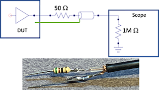
Source series termination of a coaxial cable is a low-cost alternative for probing low-voltage, high-bandwidth signals.
Figure 1: The source series termination method is
a low-cost alternative for probing low-impedance,
fast-switching sources.

In an earlier post, we discussed the limitations of  Using 50-Ohm Coax from DUT to Oscilloscope  with low-voltage, high-bandwidth signals, like power rails. In this post, we’ll explain how to build your own, low-cost power rail probe to serve the purpose.

The source series termination method is a good alternative for probing a low-impedance, fast-switching source, comprising a 50-ohm resistor in series between the DUT and the coaxial-cable connection. The coaxial cable is then connected to the oscilloscope’s analog input set for 1 megaohm termination. An equivalent circuit model and a simple implementation appears in Figure 1.

15 June 2020

What Every Oscilloscope User Needs to Know About Transmission Lines

Eric Bogatin, Signal Integrity Evangelist, Teledyne LeCroy

Measured voltage at the oscilloscope from a fast edge, low impedance DUT, with the oscilloscope at 1 megaohms (left) and 50 ohms (right).
Figure 1. Measured voltage at the oscilloscope from a
fast edge, low impedance DUT, with the oscilloscope at
1 megaohms (left) and 50 ohms (right).
It is easy to take a measurement with an oscilloscope and see a voltage waveform on the screen. It is sometimes hard to take a measurement without artifacts and interpret all the details of the measurement. 

Whenever you measure a signal with a rise time shorter than about 20 ns, assuming a 1 m long coax cable, transmission line effects should pop to the top of your list of potential artifacts to consider and avoid. 

08 June 2020

Charting High-Resolution Oscilloscope Performance


Eric Bogatin, Signal Integrity Evangelist, Teledyne LeCroy

Signal measured by 8-bit and 12-bit oscilloscope.
Figure 1. 8-bit vs. 12-bit oscilloscope waveforms.
There are hundreds of different oscilloscope models from a dozen different vendors. How do you make sense of all of their different features to pick the one instrument right for your application?  Here is a simple way of comparing high-resolution oscilloscopes.

High-resolution usually refers to the vertical resolution, the quantization of a waveform into a fixed number of vertical levels measured by the oscilloscope's Analog-to-Digital Converter (ADC). The more bits of vertical resolution, the more levels and the more detailed the waveform rendered. The earliest digital storage oscilloscopes (DSO) started as 8-bit resolution, or 256 vertical levels. But in the last ten years, as ADC chip technology got faster, higher resolution appeared in the industry, pioneered by Teledyne LeCroy.  Now, many oscilloscopes come with 10-bit and 12-bit vertical resolution. Why would you want higher resolution? The answer: the ability to see lower level signals and better dynamic range. An example of the difference between the same signal measured with an 8-bit and 12-bit oscilloscope is shown in Figure 1. 

01 June 2020

USB4 Electrical Testing: Where Are We?

Preliminary drafts of the USB4 Compliance Test Specifications (CTS) were released to USB-IF work group members in early 2020 covering the electrical through protocol layer testing of USB4 router assemblies captive cable devices. These CTS documents define the required testing for USB4 hosts, hubs, and peripherals that make up the USB4 ecosystem.  Thunderbolt 3 (TBT3) is also supported in USB4 end products and is tested using the existing TBT3 Host/Device CTS.

While the electrical test methodologies are similar to previous USB 3.2 compliance tests, USB4 is largely based off the TBT3 physical layer, and these test methods have been adopted. Here, we summarize the USB4/TBT3 test approach called out in the aforementioned documents.

USB4 Transmitter Testing

Figure 1. Test points TP2 and TP3 for USB4 Electrical Compliance Testing (Source: USB-IF)
Figure 1. Test points TP2 and TP3 for USB4
Electrical Compliance Testing (Source: USB-IF)
Presently, there is no SIG-TEST software for performing transmitter (Tx) testing, although it is anticipated that one will be released by the USB-IF in the future. All Tx tests performed by QPHY-USB4-TX-RX utilize Teledyne LeCroy methods, with measurements made directly by the oscilloscope.

Figure 1 shows the Test points defined in the CTS for physical layer testing. Testing of the Tx-side is  similar to those performed for USB 3.2 in that the signal is captured at the connector (TP2), where many measurements are defined. Then, a passive cable model is embedded and equalization is applied to result in TP3 measurements.