You need to test, we're here to help.

You need to test, we're here to help.

27 February 2023

The Case for CAN XL in 10 Mbit/S In-vehicle Networks

CAN XL has recently emerged as a contender in the 10 Mbit/S in-vehicle network space, along with 10Base-T1S Automotive Ethernet. What does CAN XL bring to earn its place on the vehicle bus?

CAN XL builds upon the foundation of CAN and CAN FD, both protocols with a long history in the automotive industry. Figure 1 summarizes the characteristics of the three CAN variants.
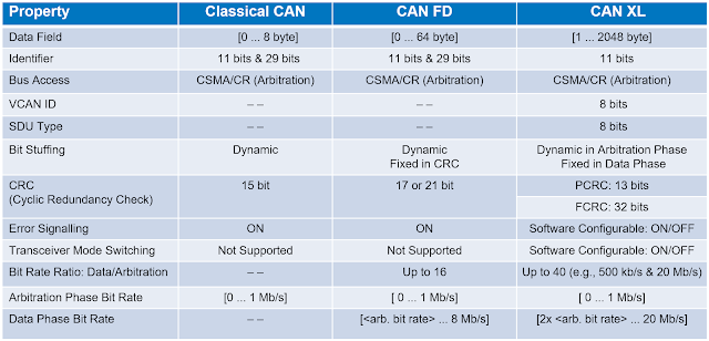
Figure 1. A comparison of the characteristics of CAN, CAN FD and CAN XL
Figure 1. A comparison of the characteristics of CAN, CAN FD and CAN XL.

CAN XL increases throughput with a Fast Mode bit rate of 20 Mbit/S in the data phase, while it operates at 1 Mbps in the arbitration phase (those fields other than data). Another feature contributing to the improved bandwidth of CAN XL is the increased data field maximum length of 2048 bytes compared to 64 bytes for CAN FD and 8 bytes for classic CAN.

20 February 2023

The Evolution of In-vehicle Network Architectures

The drive for fuel-efficient and safer vehicles opened the door to electronic control in vehicles, which in turn led to the deployment of In-vehicle Networks (IVN).  IVNs have become the backbone of modern vehicles. The volume of data flowing through these networks is increasing exponentially with demands for electric vehicles, advanced driver assistance systems (ADAS), radar, lidar, infotainment systems, cameras and vehicle-to-vehicle communications systems.  

To meet this need, the automotive industry—working with technology suppliers—has developed specialized communications protocols and application-specific extensions to existing network technologies, standardized under the aegis of organizations like ISO and IEEE, and it continues to investigate new topologies and protocols to improve performance, increase reliability and lower the costs of IVNs. Two recent developments have filled a longstanding gap in IVN architectures: CAN XL (up-to-20 Mbit/S extended length CAN) and 10Base-T1S (10 Mbit/S single-pair Ethernet), both of which operate in the 10 Mbit/S network space. What problems do these protocols solve and what opportunities do they present for IVN design?

13 February 2023

Making New PCIe 6.0 Transmitter Equalization Measurements with Your Oscilloscope

Figure 1. Transmitter equalization test results for preset Q1.

PCI Express® 6.0 achieves its 64-GT/s data rate, double that of PCIe® 5.0, by moving from non-return-to-zero (NRZ) signaling to four-level pulse-amplitude-modulation (PAM4) signaling. This results in the need for more complex algorithms for voltage and timing measurements.

The latest release of SDAIII software for Teledyne LeCroy oscilloscopes lets you easily measure response at different transmitter equalization presets to confirm that Tx EQ is achieving the specified levels prior to taking your DUT for compliance testing. The Tx EQ measurement feature works with NRZ signals and, if you have the additional SDAIII-PAMx option, with PAM3 and PAM4 signals, too.

Transmitter Equalization Coefficients and Presets Measurement

In PCIe 6.0, transmitter equalization measurements are performed on the new PAM4 Compliance Pattern signal using the AC method that was first introduced in PCIe 5.0.

08 February 2023

Removing Oscilloscope Noise from PCIe 6.0 Compliance Pattern Measurements

Figure 1. The new SDAIII-PCIE6 option offers three methods for removing oscilloscope noise from PCIe 6.0 Compliance Pattern measurements as required by the standard.
Figure 1. The new SDAIII-PCIE6 option offers
three methods for removing oscilloscope noise
from PCIe 6.0 Compliance Pattern measurements
as required by the standard.
The new SDAIII-PAMx and SDAIII-PCIE6 options for Teledyne LeCroy oscilloscopes enable you to quickly make new PCIe 6.0 noise measurements SNDR and RLM with the oscilloscope baseline noise removed, as required by the standard.

Here's a brief description of the three, proprietary noise removal methods from which you can choose.

Manual Method

Manual uses the specified amount of oscilloscope noise for the šœŽscope variable in the SNDRnr formula (described in the last post). This method is useful if you have previously measured your oscilloscope baseline noise and know what value to enter.

06 February 2023

New PCIe 6.0 Compliance Pattern Measurements

PCI Express® 6.0 features significant changes from PCIe® 5.0. In particular, PCIe 6.0 achieves its 64-GT/s data rate, double that of PCIe 5.0, by moving from non-return-to-zero (NRZ) signaling to four-level pulse-amplitude-modulation (PAM4) signaling. Consequently, PCIe 6.0 requires some new test methodologies and patterns, including a new PAM4 Compliance Pattern that finds use in multiple measurements.

Figure 1. The new PCIe 6.0 Compliance Pattern signal. Click any image to enlarge.

The new Compliance Pattern is used for calculating signal to noise and distortion ratio (SNDR), as well as ps21TX (the package insertion loss) and the transmitter ratio of level mismatch (RLM). In addition, it is used to measure transmitter equalization coefficients.

25 January 2023

Eliminating DC Resistively Coupled Noise: A Signal and Power Integrity Tutorial

Figure 8. The measured voltage noise on the victim trace, on the other side of the ground plane gap, showing no resistively coupled cross talk on the order of 10 uV, the noise floor of the measurement.
Figure 8. The measured voltage noise on the victim
trace, on the other side of the ground plane gap,
showing no resistively coupled cross talk on the
order of 10 uV, the noise floor of the measurement.

The following is excerpted from Professor Eric Bogatin's article in the Signal Integrity Journal, The Case for Split Ground Planes. Reprinted by permission of Signal Integrity Journal.

This section continues from the discussion on Inductively Coupled Noise and Resistively Coupled Noise.

. . .

When we cut a gap in the return plane, there will be no DC current flow across the gap. There will be magnetic field coupling across the gap which is why we still see significant mutual inductance coupling between the aggressor and victim across the gap. The gap has only a small impact on this noise.

However, we would expect there would be no resistively coupled noise on the victim trace on the other side of the ground plane gap. In Figure 8, the resistively coupled noise is measured with the same scale and averaging as the noise on the victim line with no gap. The noise floor of this measurement is about 10 uV. To this level, there is no measurable resistively coupled noise, a significant reduction. 

23 January 2023

Inductively Coupled Noise and Resistively Coupled Noise: A Signal and Power Integrity Tutorial

Figure 6. Measuring the inductively coupled noise on the victim trace adjacent to the aggressor signal with no gap and separated by a gap. The inductively coupled noise is reduced by about 40% on the victim trace separated by a gap. This is a small impact.
Figure 6. Measuring the inductively coupled noise
on the victim trace adjacent to the aggressor
signal with no gap and separated by a gap.
The inductively coupled noise is reduced by
about 40% on the victim trace separated by a gap.
This is a small impact.

The following is excerpted from Professor Eric Bogatin's article in the Signal Integrity Journal, The Case for Split Ground Planes. Reprinted by permission of Signal Integrity Journal.

This section continues from the discussion on Return Current at Low Frequency.

. . .

Inductively Coupled Noise

In a plane, at frequencies below about 10 kHz, return currents will not flow under the signal path, but will spread out in the return plane. Above 10 kHz, the return currents are localized under the signal paths. 

When we have two adjacent signal paths that are over a wide, continuous plane, they will show inductive cross talk at high frequency. Even with minimal overlap of the return currents, there is still loop mutual inductance between the two signal-return paths. This inductive noise is driven by the changing current, the dI/dt, in the aggressor signal-return path, which will get smaller at lower frequency.

18 January 2023

Return Current at Low Frequency: A Signal and Power Integrity Tutorial

Figure 3. Specially configured coax cable with the front and back of the shield shorted together.
Figure 3. Specially configured coax cable with
the front and back of the shield shorted together.

The following is excerpted from Professor Eric Bogatin's article in the Signal Integrity Journal, The Case for Split Ground Planes. Reprinted by permission of Signal Integrity Journal.

This section continues the discussion in Signal Return Paths of the equation,

Z = R + jš›šL

Where:

Z is the loop impedance of the current loop path, 

R is the series resistance of the loop and 

L is the loop inductance of the path.

. . .

At low frequency, when the loop impedance is dominated by the R term, the current distribution in the return plane is NOT driven by the loop impedance, it is driven by the loop resistance. In the signal path, the current will spread out uniformly as any filament path in the signal conductor will have roughly the same resistance.

But the current filaments in the return path with the lowest R will be those which are shortest. This means that return currents will take the shortest paths, independent of the signal paths. As frequency increases, the return current will redistribute to transition from the path of lowest R to the path of lowest L. 

16 January 2023

Signal Return Paths: A Signal and Power Integrity Tutorial

Figure 1. Current distribution in the signal and return conductors at three different frequencies. The current redistribution at higher frequency is driven by the currents taking filament paths with the lowest loop inductance.
Figure 1. Current distribution in the signal and
return conductors at three different frequencies.
The current redistribution at higher frequency
is driven by the currents taking filament paths
with the lowest loop inductance. 
The following is excerpted from Professor Eric Bogatin's article in the Signal Integrity Journal, The Case for Split Ground Planes. Reprinted by permission of Signal Integrity Journal.

. . .

Why Continuous Return Path Planes

The first step in engineering interconnects to reduce noise is to provide a continuous, low impedance return path to control the impedance, which controls reflection noise, and reduce the cross talk between signals that also share the same return conductor. 

A wide, continuous ground plane adjacent to a signal trace will be the lowest cross talk configuration. Anything other than a wide plane means more cross talk between signal paths sharing this return conductor. This means, never add a split or gap in the return path. You would run the risk of a signal trace inadvertently crossing this discontinuity.

If a signal crosses over a split ground plane, there are two effects which compound each other. Crossing a split creates a higher impedance path for return currents that must cross the split and forces return currents from multiple signals to overlap through the same, higher impedance, common path.