 |
Figure 1: An example
of a GFCI |
The ubiquitous ground fault circuit interrupter (GFCI), a fast-acting circuit breaker, has saved countless individuals from serious injury or death when they've inadvertently entered the low-resistance ground path of an electrical device or outlet. It's important to measure precisely the amount of time that elapses from when the 60-Hz cycle is present to when the GFCI disables the ground path. Other tests include determining the start, stop, and duration of the GFCI's tripping time. Let's take a look at the challenges these measurements present.
Because the 60-Hz cycle is the time when a current is potentially flowing through someone's body on its way to ground, getting a GFCI device certified requires that this period is short enough to ensure that a short circuit is not a killer.
 |
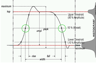
| Figure 2: IEEE definitions of a standard pulse |
The challenges in these measurements come from a couple of factors. For one, the exact start and
stop times of a burst are variable. For another, the measurement is typically being made on a non-integer value of the waveform's cycles. According to the IEEE's definition, a pulse width measurement begins at the start of the cycle and ends when it ends. Referring to Figure 2, those points are demarcated by the green circles. Meanwhile, oscilloscopes determine pulse parameters from the top and base values, with pulse widths, periods, and burst durations measured to the nearest (integer) cycle. The IEEE pulse definitions do not provide the measurements required for GFCI testing.
 |
Figure 3: An example of timing measurement
using IEEE pulse parameters |
Another way of looking at this is to say that according to the IEEE, the period of a pulse is measured between rising edges (Figure 3). If you have a non-integer value of a waveform cycle (such as on the left at the red arrow), this portion of the waveform capture is not measured by any oscilloscope that measures period. Yet, these portions are critical to the GFCI tripping time measurement.
The problem is complicated further by the fact that burst lengths vary from acquisition to acquisition, as does the exact size and shape of the non-integer portion. One might use cursors to measure burst length, but doing so would require the user to manually reposition the cursors for each varying pulse length. And, suppose the pulse has a false starting edge? Misplacing the cursors in such a case will return an incorrect measurement.
 |
Figure 4: Parameter scripting automates determination
of the burst's start and end positions to 1-ns resolution |
Solving this problem, as well as any other special or corner cases that may arise, calls for parameter scripting, which can measure the exact burst length to 1-ns accuracy (a tutorial on Visual Basic scripting for Teledyne LeCroy oscilloscopes
may be found here). The script can be written so as to dynamically assign zoom positions to the waveform based on the starting position. Referring to Figure 4, zoom trace Z1 displays a label showing the start of the burst waveform that was automatically determined by the script. The script also labels the start of the burst on the full waveform trace. Likewise, Z2 shows the end position. The parameter table at bottom shows the duration of the pulse (234 ms) to 1-ns resolution.
As a side note, the determination of the burst duration to such fine resolution demands use of an oscilloscope with
12-bit ADCs. Unfortunately, the quantization noise inherent to 8-bit oscilloscopes makes it impossible to so accurately place the start and stop markers.


1 comment:
1ns resolution is at least 4 bits overkill on a 234 ms pulse with (evidently) 3 sigfigs.
8 bit ADC is adequate with correct clock rate. Inductance will affect overshoot, but using a better trigger filter to sample waveform so that inductance is negligible compared to RC delay
Post a Comment