 |
| Figure 1: A representative block diagram of a mixed-signal embedded system |
Further, mixed-signal design touches a large number of application areas, including appliances, audio, automotive, avionics, consumer electronics, industrial equipment and automation, medical equipment, military hardware, networking equipment, motor control, power conversion, power supplies, and more. So it behooves just about any designer or design team to ensure that they have test and measurement equipment that is up to the task.
 |
| Figure 2: Analog/digital cross-pattern triggering allows creation of complex analog/digital pattern triggers |
Besides the obvious addition of some number of digital input lines, a mixed-signal oscilloscope provides such capabilities as analog/digital cross-pattern triggering (Figure 2). With it, you can create complex analog and digital pattern triggers to isolate problems. It enables searching for timing errors by specifying a trigger for an invalid digital state.
Another key advantage of a mixed-signal oscilloscope is digital pattern search and find. This capability allows the user to search across many digital lines to find specific digital patterns. Once the desired pattern is found, oscilloscopes such as Teledyne LeCroy's HDO-MS models enable you to automatically zoom in on the relevant portion of the waveform. Digital pattern search and find is ideal for searching for timing problems where invalid patterns may occur.
 |
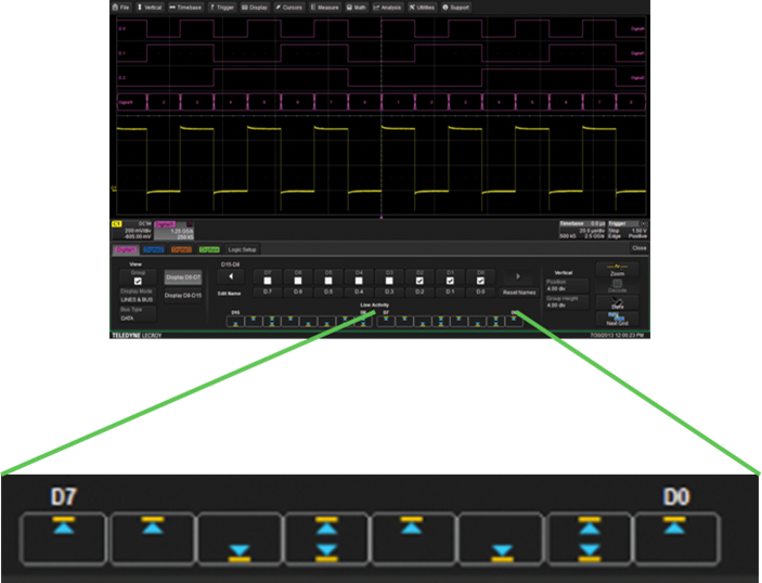
| Figure 3: Activity indicators show the current state of all digital lines at a glance |
A useful feature of the HDO-MS oscilloscopes is activity indicators for the digital lines (Figure 3). These indicators let you see the current state (high, low, or transitioning) of all of the digital lines at a glance. They can also help you quickly identify lines that are incorrectly hooked up, such as to ground or to a power-supply line. The indicators are active even when the oscilloscope is not triggering.
For these reasons, among others, mixed-signal design and debug is best approached with an instrument that is suited for the task, such as the Teledyne LeCroy HDO-MS (an added benefit on the analog side of the equation is HD4096 technology). A mixed-signal oscilloscope integrates all of the best aspects of a traditional oscilloscope and a dedicated logic analyzer, and thus is among the best options for the mixed-signal testbench.
No comments:
Post a Comment