 |
| Figure 1. Three options for connecting a TDR to a UTP. |
Q: For the UTP
measurement, do you need to connect the SMA connector shield grounds together?
A:
Yes.
It’s very important to make sure the grounds are connected at the cable
connectors.
There are really three ways the connections can be made from a differential
TDR to the UTP cable. These three options are shown clockwise from left to right in Figure 1.
- Connect the two wires as a signal and return to one SMA. This treats the differential pair as a single-ended transmission line. We would expect that a single-ended measurement in this case would be the same impedance as the differential impedance, as measured by a 2-port set up.
- Connect the two return paths at the SMAs.
- Keep the two returns of the SMA separated.
In principle, it should be OK to keep the returns isolated or connected.
After all, once the signal is launched into the twisted pair, it’s all about
the UTP cable.
In practice, though, what we are really doing is launching a
single-ended signal into first one line, measuring all the S-parameters, and
then launching into the other line and measuring all the S-parameters. We
combine the S-parameters to calculate the mixed mode S-parameters. The, we convert the S-parameters into the time
domain response.
This basically means we are going to subtract two big numbers, the
single-ended return loss and the coupling term, to get a smaller number, the
differential return loss. The result is very sensitive to the uncorrelated
noise in the two measurements. The return losses are all about the huge
impedance discontinuity of the signal path through each wire and the return
path being so far away, plus the coupling to the adjacent wire.
By connecting the grounds together at the SMA, we reduce the stray
fields from the two cables of the TDR, and thus are able to get less noise and
a more stable measurement. When we subtract the two big numbers to get the
differential return loss, it is a cleaner result.
 |
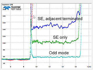
| Figure 2. Measured TDR response of UTP. |
Using this technique, we are able to get very clean, very reproducible
results that make a lot of sense. Figure 2 shows the measured TDR response from
the UTP. In this example, the top, blue trace is the single-ended impedance of
one wire in the UTP, with the other wire connected to the TDR, but just
terminated. This is the single-ended response with a 50 Ohm resistor in series
with the second line’s impedance. This impedance is about 100 Ohms + 50 Ohms.
The middle trace in green, is the single-ended response of the two wires
treated as a single-ended transmission line, in a single-ended TDR measurement,
using both wires soldered to the same SMA. This is the first configuration in Figure
1. This treats the two wires twisted together as a single-ended transmission
line. The impedance is about 100 Ohms. This is the same as the differential
impedance of the pair.
In the third case, in teal, the two wires are driven with a differential
signal, but the TDR response of just one line is measured. This is the odd mode
impedance of one line that is part of the pair. The odd mode impedance is 50
Ohms. We would expect the differential impedance of the pair to be 100 Ohms.
This is exactly what we measure with the single-ended measurement.
For more information on this topic, see the on-demand webinars:
1 comment:
cool! i thought it was simple to just connect the terminals, i know about noise but i didn't know this affected the signal in such a small device.
Post a Comment