 |
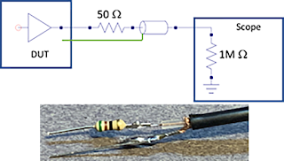
| Figure 1: The source
series termination method is a low-cost alternative for probing low-impedance, fast-switching sources. |
In an earlier post, we discussed
the limitations of Using 50-Ohm Coax from DUT to Oscilloscope with low-voltage, high-bandwidth signals,
like power rails. In this post, we’ll explain how to build your own, low-cost power
rail probe to serve the purpose.
The source series termination method is a good alternative for probing a low-impedance, fast-switching source, comprising a 50-ohm resistor in series between the DUT and the coaxial-cable connection. The coaxial cable is then connected to the oscilloscope’s analog input set for 1 megaohm termination. An equivalent circuit model and a simple implementation appears in Figure 1.
When measuring most high-bandwidth signals, 50 ohm is
the recommended input impedance to the oscilloscope. This does not hold true,
however, for power rails. For one, with 50-ohm input impedance, the maximum
voltage one can probe is typically around 5 V. Higher voltages will dissipate
too much power in the 50-ohm resistor, and the oscilloscope may suffer damage. For
another, using 50-ohm input impedance will introduce a DC load to the DUT.
 |
| Figure 2. Equivalent
circuit for a direct coax connection to a 1 megaohm oscilloscope input termination. |
The answer to this problem: add a 50-ohm source
series termination at the end of the coaxial cable. As a result, half of the
source voltage is initially launched into the coax cable, which reaches the
oscilloscope’s 1 megaohm input termination and reflects back. The initial
voltage measured by the oscilloscope is 2x the launched voltage, which is
exactly the voltage of the source.
 |
| Figure 3. Startup of 5 V power supply with direct coax connection to oscilloscope 1 megaohm input (left), and with a 50-ohm source series termination added (right). |
No comments:
Post a Comment