You need to test, we're here to help.

You need to test, we're here to help.

22 May 2014

The Effects of Passive Probe Ground Leads

Teledyne LeCroy's PP108, a representative passive probe
Figure 1: Teledyne LeCroy's PP108,
a representative passive probe
When you open the box containing your shiny new oscilloscope, one of the items you'll likely find inside is a set of basic 10:1 passive probes (Figure 1). Those probes have a ground lead that you'll want to use when you make measurements. Your probe has a bandwidth specification that's probably somewhere between a few hundred megahertz to 1 GHz; that spec was obtained at the factory with a specialized test jig having a specific ground inductance and source impedance. Now, the way in which you connect your ground lead can have a big impact on the real-world bandwidth and response of the probe.

15 May 2014

Back to Basics: S-parameters
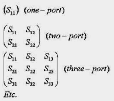
S-matrices for one-, two-, and three-port RF networks
Figure 1: S-matrices for one-, two-,
and three-port RF networks
Suppose you have an optical lens of some sort onto which you shine a light with a known photonic output. While most of the incident light passes through the lens, some fraction of the light is reflected and some is absorbed (the behavior is also dependent on the wavelength of the incident light). You'd like to characterize that lens: Exactly how much light was reflected? How much passed through? What is it about the lens that prevented all of the light from passing through?

16 April 2014

Is Your Testbench Mixed-Signal Ready?

A representative block diagram of a mixed-signal embedded system
Figure 1: A representative block diagram of
a mixed-signal embedded system
Mixed-signal design is ubiquitous these days, with hybrids of digital and analog circuitry turning up everywhere. A typical mixed-signal designer may be a hardware or software engineer with specific needs. They may be working with 4-bit, 8-bit, 16-bit, and 32-bit microcontrollers in a single embedded controller or across several embedded systems. They need to capture a host of different signal types and serial-data protocols and understand timing relationships between them. Then there's all the different sensor signals, power-supply signals, and PWM control signals to guarantee embedded system performance and reliability.

09 April 2014

Applying Multi-Stage, Multi-Rate Digital Filtering
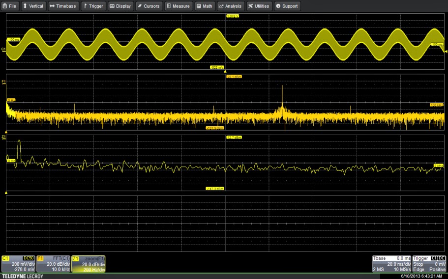
63-kHz signal with 60-Hz component
Figure 1: The input signal shows both the desired 63-kHz signal
along with a 60-Hz component. Zoom trace Z1 shows the
60-Hz component in detail.
A while back, we posted some basics on how to apply digital filters to sort out signals with undesirable elements riding on top of them, i.e. a square wave that's being corrupted by a sinusoidal signal creeping in from somewhere in your system design. Now, let's look at how to extend the range of cutoff frequencies for digital filters, allowing them to be used even more effectively.

02 April 2014

Understanding Probe Calibration Methods (Part II)

Experimental setup
Figure 1: Experimental setup for comparing a
source-referred signal to an unloaded signal
As many engineers and techs know, there's ample room for confusion when it comes to a proper understanding of oscilloscope probe loading. In an earlier post, we covered probe calibration methods and tried to sort out terms such as calibration, correction, compensation, and de-embedding.

26 March 2014

Using Digital Filters

Using a band stop filter
Figure 1: Using a band stop filter to remove a 5-MHz sine
wave from a 4-MHz square wave
In a perfect world, all of the signals we wish to view on our oscilloscopes would be as pure as the driven snow. However, in most scenarios, reality intervenes. As we know, everything in a system is an antenna, some being more efficient than others in terms of radiation and/or reception. Hey, crosstalk happens, and if you've got a sine wave and a square wave co-existing in the same general vicinity, it could make a true evaluation of the square wave difficult to do. But how do we get that nasty sine wave coming from one circuit to stop jumping on the  back of the square wave in another?

19 March 2014

Tips and Tricks: Rescaling for Non-Voltage Measurements

Using rescale to read a current probe's output in Amps
Figure 1: Using math rescale to read a current probe's
output directly in Amperes
As we know, an oscilloscope is essentially an instrument that measures a constantly varying voltage as a function of time. Those measurements are subsequently analyzed to derive other properties of the input signal, such as frequency, amplitude, rise/fall times, and so on. But what about measurements of other electrical quantities as a function of time?