CAN XL has recently emerged as a contender in the 10 Mbit/S in-vehicle network space, along with 10Base-T1S Automotive Ethernet. What does CAN XL bring to earn its place on the vehicle bus?
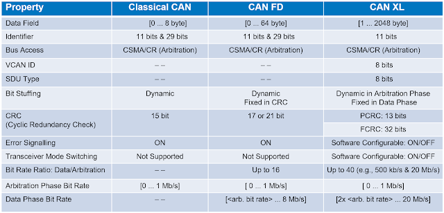
CAN XL builds upon the foundation of CAN and CAN FD, both protocols with a long history in the automotive industry. Figure 1 summarizes the characteristics of the three CAN variants.
 |
| Figure 1. A comparison of the characteristics of CAN, CAN FD and CAN XL. |
CAN XL increases throughput with a Fast Mode bit rate of 20 Mbit/S in the data phase, while it operates at 1 Mbps in the arbitration phase (those fields other than data). Another feature contributing to the improved bandwidth of CAN XL is the increased data field maximum length of 2048 bytes compared to 64 bytes for CAN FD and 8 bytes for classic CAN.
All three CAN variants use Non-Return-to-Zero (NRZ) encoding. This means there can be long intervals where there are no edges in the data, which poses a problem for clock recovery where periodic edges are needed to “lock on” and synchronize to the data. CAN and CAN FD use a method called stuff bits to assure that clock edges are available. Older CAN formats use dynamic bit stuffing, where if five bits are transmitted with the same logical state, a stuff bit of the opposite logical state is added to the data stream. CAN XL uses dynamic bit stuffing in the arbitration fields. In the data field, which operates at a higher clock rate, CAN XL uses fixed bit stuffing after every ten bits. Because we can predict the length of the data field with a fixed stuff bit period, data interpretation is faster, a benefit at the higher data rate of CAN XL.
The frame format in CAN XL has also been lengthened and improved to allow greater flexibility. Where CAN and CAN FD have the identifier in the arbitration field, which plays a role in the arbitration of priority, CAN XL now has an 11-bit field called Priority ID, which handles priority only. Addressing is handled by another method in the control field.
 |
Figure 7.
The CAN “Daisy Chain” |
CAN utilizes a Daisy Chain network topology, where devices are connected to a central bus with varying length stubs. CAN XL allows stubs to be up-to-one meter in length. A major advantage of CAN XL, which applies to all the CAN variants, is that this topology is easily scalable. Modifying an existing system involves simply adding CAN network devices with distinct IDs to the bus.
Also common to all versions of CAN is the use of dominant and recessive states to signal priority. The dominant state is the higher differential voltage state. The recessive state is the lower differential voltage state.
The bus driver is capable of actively driving the bus to the dominant state, while the return to the recessive state depends on resistive discharge through the terminations. This arrangement of using the dominant and recessive states allows other nodes to override bits, thereby defining the priority of the different IDs. If a node is sending dominant zeros, then the other nodes know that ID has a higher priority. Overriding bits are also used in the acknowledgment field to indicate the status of received data.
But this technique has a big disadvantage, especially at higher speeds, because only the dominant state is really driven. The recessive state has only passive resistors to pull signal to the recessive voltage level. If there is an impedance mismatch on the bus, it is possible to see a lot of reflections, which can result in ringing. At lower speeds it is not an issue, because the settling point can be defined in CAN and the sampling point set at a time where it is easy to detect a 1 versus a 0. At higher speeds, however (e.g., above 2 Mbit/S), it is nearly impossible to detect a 1 versus a 0 in the presence of reflections.
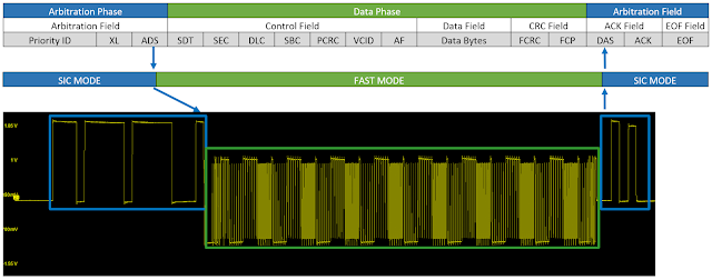
To improve signal fidelity, CAN XL implements a new Fast Mode. In Fast Mode, both logic states are driven symmetrically, and the receiver threshold is set to 0 volts differential with a tolerance of ±100 mV. When the device switches from the arbitration phase to Fast Mode for the data phase, there a change in the amplitude and in the offset. There is also a change in impedance as both states are driven from a low impedance source. Because both states are driven, they are described in terms of 1 and 0 levels, similar to other standards, rather than dominant/recessive. There is much less ringing and a better margin for the receiver to detect a 1 versus a 0. Fast Mode is applied only to the data phase of the CAN XL frame, as shown in Figure 3.
 |
| Figure 3. Fast Mode is applied to the high-speed data phase of a CAN XL frame to enhance signal integrity. |
The selection of one bus protocol over another when designing an IVN depends on many things. Certainly, if previous designs already use CAN and CAN FD, then it may be easier to simply extend them using CAN XL rather than switch to another protocol. For example, many specialty vehicles (e.g., fire trucks) are customizations of a standard base design. If CAN is already used in the basic vehicle, it will likely be implemented for any new functionality that is added during customization.
Even some functions that normally require higher speed data, such as cameras for ADAS, can be accomplished using CAN XL. For example, in lower cost vehicles that do not utilize high-speed data links, CAN XL adds capabilities like support for compressed video, which can be used for back up cameras.
For these and other reasons, CAN is likely to be with us for quite some time, even if the trend in automotive design is toward a single-network vehicle architecture. Learn more in our free, on-demand webinar, Fundamentals of 10 Mb/s In-vehicle Networks.
No comments:
Post a Comment