 |
| Figure 1: Working out the optimal combination of Tx emphasis presets and receiver CTLE settings |
The next step in this procedure is to determine the correct transmitter emphasis preset and amount of receiver continuous time linear equalization (CTLE) to compensate for the 19-dB channel loss (Figure 1). We begin by employing what we know to be our two best transmit presets, P5 and P6. We acquire seven waveforms with each preset on the oscilloscope through the channel, and run each of seven CTLE presets.
 |
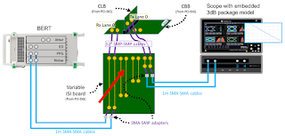
| Figure 2: Connection schematic for finding marginal channel |
We end up with 98 SigTest instances that have to be run. Each of those runs takes about two minutes, so in aggregate this step can end up taking some three hours. Fortunately, Teledyne LeCroy's LabMaster 10Zi-A oscilloscope can run 20 instances of SigTest in parallel, reducing this step to perhaps 15 to 20 minutes.
Having arrived at optimal Tx and Rx equalization settings, we now begin to increase the channel loss in 0.5-dB increments. We will be using the connection schematic shown in Figure 2.
At some point, we will violate our final eye height and width calibration targets. When that happens, we stop incrementing the channel loss and move back one increment. Now we've found the maximum amount of loss we can have in the channel before we make the eye too small for the receiver test to be properly performed. If we find that we have not violated the calibration targets, we stop at a total channel loss of 30 dB, which is 2 dB higher than the maximum allowable total channel loss of 28 dB.
Now we run the Tx emphasis preset and Rx CTLE scan yet again (yes, 98 more instances of SigTest) to ensure that we still have the optimal presets on the BERT for the channel. So in effect, we are emulating the behavior of a good device receiver that is optimizing its receiver CTLE.
At last, we've arrived at a channel with the maximum allowable loss that we can tolerate in our system. Next, we need to converge on final eye height and width values. We're looking for an eye height from 13.5 to 16.5 mV and an eye width from 18.25 to 19.25 ps; in other words, a pretty small target. However, we should already be close due to the just-completed process of varying the channel loss. Now we will add or subtract very small increments of differential-mode noise and sinusoidal jitter to converge on that final eye height and width.
 |
| Figure 3: The actual bit rate-error test for receiver link- equalization performance must result in no more than one error in 10-12 bits. |
After this time-consuming calibration process, we can now perform the actual test of receiver link equalization. First, the DUT must be negotiated into loopback by the BERT under the stress conditions of the calibrated channel and jitter/noise-imbued sinusoidal signal. The DUT/BERT negotiation must take place through the "recovery path," where the device performs link training and requests the optimal Tx emphasis preset from the BERT. The criteria for the bit error-rate test is no more than one error in 10-12 bits.
This completes the review of the PCIe 4.0 receiver link-equalization test. It requires the full spectrum of the test equipment's sophisticated capabilities. You'll need an oscilloscope with at least 25 GHz of bandwidth, channel de-embedding capabilities, and, ideally, multicore processing capabilities. The BERT must bring the proper bit-rate capabilities, adequate jitter and noise sources, emphasis capabilities, and protocol-layer link training and state-machine analysis.
We'll conclude our overview of PCIe 4.0 compliance testing with the PLL bandwidth test in our next post.
Earlier posts in this series:
Introduction to PCIe 4.0 Electrical Compliance Test
Gearing Up for PCIe 4.0 Electrical Compliance Test
PCIe 4.0 Transmitter Electrical Testing (Part I)
PCIe 4.0 Transmitter Electrical Testing (Part II)
PCIe 4.0 Transmitter Link-Equalization Testing
PCIe 4.0 Receiver Link-Equalization Testing (Part 1)
No comments:
Post a Comment