 |
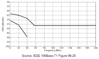
| Figure 1: The specified pass/fail mask for the transmitter power spectral density test |
This test is performed using test mode #5, which is a PAM-3 transmission of a random data sequence. The specification supplies upper and lower test limits, and the test can be performed with a spectrum analyzer or an oscilloscope with spectral-analysis capabilities. It verifies that the power spectral density does not escape the boundaries of a specified pass/fail mask (Figure 1).
 |
| Figure 2: Averaging the power spectral density over 60 seconds gives a good indication of frequency content |
Performing the PSD test with an oscilloscope entails using the instrument's FFT math function, setting it to calculate power spectral density. We average the power spectral density measurement over a 60-second acquisition (Figure 2). Averaging gives us a good determination of the signal's frequency content, and also averages out any random noise. The test concludes by applying the specified pass/fail mask.
 |
| Figure 3: Testing for transmitter peak differential output ensures that the signal stays within the 2.2 V pk-pk limit |
The test is rather simple. Your oscilloscope has a peak-to-peak voltage parameter measurement. Turn it on and check that the signal's peak-to-peak voltage amplitude does not exceed the 2.2 V pk-pk limit in the specification.
We'll conclude our series on Automotive Ethernet test in an upcoming final post with a look at test equipment requirements.
No comments:
Post a Comment