 |
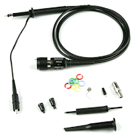
| Figure 1: The 10x passive probe becomes a better measurement tool when we understand its limitations |
In fact, we'd like our probe-cable-oscilloscope measurement system to be perfect, possessing:
- A mechanical interface that conforms to the DUT
- Infinite impedance from the DUT's perspective, and 50-Ω impedence when necessary
- Infinite bandwidth
- Infinite signal-to-noise ratio (SNR)
- Flexible enough to fit all scenarios
- Priceless (as in "free").
The probe that every oscilloscope user is likely to be familiar with is the classic 10X passive probe (Figure 1), mainly because a pair of them comes with every oscilloscope. What's going on inside those things, anyway? In taking some time to examine the 10X passive probe closely, we can better understand its limitations.
The first thing to think about in the 10X passive probe is its mechanical interface: the tips. Three commonly used tips are the mini-grabber clip, short-return clip, and coaxial BNC. In the case of the former, be aware that the whole spring-loaded part pulls off leaving the signal pin exposed. The short-return clip is handy at times when a very short return path is important to a measurement vs. the roughly 3-inch lead on the mini-grabber device. The coaxial BNC attachment lets you attach the probe directly to a female BNC receptacle when such connectors are found on the DUT.
 |
| Figure 2: Shown is an equivalent circuit schematic for a typical 10X passive probe |
Thus, we have 9 MΩ in series and the 1 MΩ of the oscilloscope, and we're looking at the voltage across that 1-MΩ resistance inside the oscilloscope's amplifier. That comprises a 10:1 voltage divider: The voltage we see is coming through the 9 MΩ + 1 MΩ/1 MΩ. And that brings up an important point about the 10X passive probe, which is that the name is a misnomer. It's not a "10X" probe, but rather it's a 1/10th probe, a 1/10th attenuating probe. The signal we see at the oscilloscope input is 1/10th the signal at the tip. Most modern oscilloscopes are smart enough to know there's a 10X passive probe hanging off of them, and to automatically convert the voltage seen on the display to the voltage seen at the tip. But we need to bear in mind that the signal hitting the oscilloscope input is 1/10th of the voltage that the probe tip sees.
Why? Because there are three problems to watch for when using a 10X passive probe due simply to the nature of the beast. First is the already-mentioned voltage divider. Seeing 1/10th of the signal at the oscilloscope input means we're giving up 20 dB of that signal. If we're limited by the oscilloscope's noise floor, our signal-to-noise ratio has just dropped by 20 dB. If it's volt-level signals we're probing, this might be a non-issue. But if our signal of interest is in the millivolt range, then that 20 dB matters. A lot.
The second problem is that we have the 9-MΩ series resistance at the tip, the 1-MΩ at the oscilloscope input, the 15-17 pF of capacitance at the input, and also some capacitance in the coaxial cable. When you sum all of this up, you arrive at a low-pass filter. The capacitance can be as much as 100 pF, and using RC = 1 MΩ x 100 pF, we arrive at a time constant of about 100 μs. That works out to a pole frequency of our low-pass filter of around 10 kHz.
This means that the low-pass filter cutoff of the probe would be 10 kHz, rendering it pretty much unusable for measuring anything of value. That's why 10X passive probes have a special built-in feature: an equalization circuit in the form of the 9.5-pF trimming capacitor across the 9-MΩ series resistance at the tip and the 17-pF capacitor at the input to the oscilloscope.
We'll dive into that equalization circuit and begin looking at the performance characteristics of the 10X passive probe in our next post.
Previous posts in this series:
Putting Probes in Perspective
2 comments:
Nice post! One question related to 10x passive probes. Why some probes manufacturers talk about 10:1 attenuation probes with 1MOhm of probe input impedance? They indicate that these probes must be used with 50Ohm Oscilloscope Input. How is it possible reach 10:1 relation with 1MOhm INput Impedance and 50Ohm oscilloscope impedance?
Thanks
Adam,
The short answer is that passive probes and most probes with <500 MHz bandwidth are coupled into the 1 MOhm input on the scope, and they are nominally 10 MOhm, so that is the 10:1 attenuation.
Our higher bandwidth probes couple to 50 Ohms.
Dr. Eric Bogatin talks more about How to Choose Between the Oscilloscope's 50 Ohm Input and 1 MOhm Input in https://blog.teledynelecroy.com/2020/08/how-do-you-choose-whether-to-use-50-ohm.html
Post a Comment