10 December 2015

Using Your Oscilloscope's X-Y Display

Shown are some common Lissajous patterns in an X-Y display
Figure 1: Shown are some common
Lissajous patterns in an X-Y display
If you're fortunate enough to own an oscilloscope with X-Y display capabilities, you have a valuable tool at your disposal. From classic Lissajous patterns to state transition diagrams for today's quadrature communication systems, X-Y plots give us a window of the functional relationships between two waveforms.

30 November 2015

Follow The Bouncing Signal

Trend plotting is a handy tool for discerning frequency-hopping patterns
Figure 1: Trend plotting is a handy tool
for discerning frequency-hopping
patterns
Signal jamming, noise generation/interference, signal interception, and other malicious RF-related activities have long been part and parcel of the electronic warfare arena. One countermeasure that is widely deployed is frequency hopping spread-spectrum (FHSS) transmission, or rapid and pseudo-random jumps of the carrier frequency in an effort to confound would-be jammers. FHSS transmission poses test and measurement challenges that we'll outline below.

18 November 2015

Analyzing RADAR Signals with Demodulation

An example of a radar signal with 1-GHz RF carrier
Figure 1: An example of a radar
signal with 1-GHz RF carrier
In the electronic warfare milieu, one of the most common RF applications is that of radar systems. Radar, which uses RF energy to determine the range, angle, and/or velocity of objects, can be used for detection of aircraft, ships, spacecraft, guided missiles, motor vehicles, weather formations, and terrain, among other things. An oscilloscope's demodulation math function is very helpful in analysis of radar signals, so let's look at a couple of examples of how to approach such measurements.

02 November 2015

Video: The Many Varieties of Oscilloscope Probes

Got a minute (OK, a minute and a half)? Take a look at this quick tutorial video that takes you through the four basic types of probes and what they're used for:


If this little thumbnail sketch whetted your appetite for more info on oscilloscope probes, we've got you covered with a series of popular blog posts on the topic:


21 October 2015

Analyzing Pulse-Width Modulation Signals

Persistence display provides a quick-and-dirty view of a PWM signal
Figure 1: Persistence display provides
a quick-and-dirty view of a PWM signal
Pulse-width modulation (PWM), a favorite technique for achieving analog ends through digital means, finds application in all kinds of end systems. Motor control might be the number-one application, but PWM turns up in telecommunications, audio systems and amplifiers, and any number of other uses. Armed with a capable oscilloscope, one can thoroughly analyze and understand the behavior of PWM circuits.

14 October 2015

Determining an RF Burst's Envelope

Demodulation is one method of determining the envelope of an RF burst
Figure 1: Demodulation is one method
of determining the envelope of an RF burst
There aren't many wireless environments more complex than that of the electronic-warfare arena. Spread-spectrum clocking, frequency hopping, jamming, you name it: It's an RF jungle out there, and signals intended for electronic-warfare applications demand precision instrumentation and skilled hands for test and measurement purposes.

01 October 2015

Taking Best Advantage of Oscilloscopes' Long Memory

Figure 1: Maintaining the maximum sample rate over more timebase settings is possible with long memory
Figure 1: Maintaining the maximum sample rate over more
timebase settings is possible with long memory
Two very important considerations when choosing a digital oscilloscope are the length of the acquisition memory and the amount of RAM available for processing of the raw data. Note that acquisition memory and RAM are not the same things, but they are still both important. The amount of acquisition memory often determines the fidelity with which an oscilloscope can record a signal. But that's only the first step; it's the instrument's processing horsepower is the key to finding signal abnormalities and characterizing circuit performance.

11 September 2015

For UART Debugging, Triggering is Key

A typical screen capture of UART serial decode/trigger software
Figure 1: A typical screen capture of UART
serial decode/trigger software
In our survey of how modern oscilloscopes and trigger/decode software (Figure 1) can ease the task of debugging embedded systems, we've covered the I2C and SPI protocols. Now we'll turn to the UART format, where triggering capabilities are of particular importance.

03 September 2015

Shaking Bugs Out of SPI Buses

Figure 1: Debugging of SPI on a Teledyne LeCroy WaveSurfer 3000 oscilloscope
Figure 1: Debugging of SPI on a Teledyne LeCroy
WaveSurfer 3000 oscilloscope
In the first post of this series, we considered some of the challenges of debugging embedded systems in general and I2C buses in particular. Modern digital oscilloscopes equipped with powerful trigger/decode software for the serial protocol in play go a long way toward easing the path to a properly functioning embedded system. Now we'll consider the particularities of the Serial Peripheral Interface and how the proper tools can make debugging SPI buses easier.

12 August 2015

Test Challenges for PAM4 Signals

The major test challenges posed by PAM4 signals
PAM4 encoding offers the advantage of doubling the bit rate in a serial data channel, doing so by increasing the number of voltage levels from two to four. It's a fairly complex modulation scheme, so it should be no surprise that it presents some test and measurement challenges.

06 August 2015

Why High Oscilloscope Sampling Rates Matter

Figure 1: Here is an example of aliasing that results from sampling a signal at less than the Nyquist rate of 2fmax
Figure 1: Here is an example of aliasing that results from
sampling a signal at less than the Nyquist rate of 2fmax
A key to accurate measurements with an oscilloscope is to ensure that the instrument maintains a high sampling rate. This applies to most measurements; conversely, for many measurements, accuracy may suffer as sample rate decreases. In the worst case, some signal components may be "aliased," meaning that the true signal shape is corrupted by the addition of bogus signal components that arise from undersampling of real signal components.

22 July 2015

Debugging I2C Buses in Embedded Systems

Debugging of I2C on a Teledyne LeCroy WaveSurfer 3000 oscilloscope
Figure 1: Debugging of I2C on a Teledyne LeCroy
WaveSurfer 3000 oscilloscope
Embedded systems became ubiquitous decades ago and are now found in everything from mobile devices to vehicles to the traffic lights that control their movements. These days, they're typically based on microcontrollers and perform some specific task(s) within a larger system, such as controlling your car's ABS system. They may or may not have any sort of user interface, and can range widely in terms of complexity and functionality.

PAM4 Test Setups Vary With Applications

Figure 1: A high-level view of PAM4 use cases
In an earlier post, we surveyed the basic properties of PAM4 signals. Now, we will examine some of the ways in which PAM4 is finding application in the real world and what test and measurement setups might look like for those applications.

15 July 2015

The Fundamentals of PAM4

PAM4 doubles the number of bits in serial data transmissions by increasing the number of levels of pulse-amplitude modulation, but does so at the cost of noise susceptibility
PAM4 doubles the number of bits in serial data transmissions
by increasing the number of levels of pulse-amplitude modulation,
but does so at the cost of noise susceptibility
As our society's hunger for data grows—not only more data, but more data delivered faster—older modulation schemes based on NRZ-type encoding grow increasingly inadequate. We need to get data from point A to point B as efficiently as possible, whether that means between chips on a PC board or from one end of a long-haul optical fiber to the other. A modulation scheme that's gaining favor in many quarters is PAM4, and in this post we'll look at the basics of PAM4 before turning to the test and analysis challenges it poses.

08 July 2015

Using Persistence Mode and Exclusion Trigger

Figure 1: By using exclusion triggering, the oscilloscope is prevented from triggering on the normal signal shape. The trigger is set to capture only pulses with widths different by at least 15 μs from the typical 325 μs.
Figure 1: By using exclusion triggering, the oscilloscope
is prevented from triggering on the normal signal shape.
The trigger is set to capture only pulses with widths
different by at least 15 μs from the typical 325 μs.
Any piano player is well acquainted with the right-most pedal on their pianos, known as the sustain or open pedal. Pressing that pedal while playing will lift all of the instrument's dampers away from the strings, allowing them to ring freely until their vibration dies out or the pedal is released.

On a digital oscilloscope, the persistence display mode is a little like the sustain pedal on a piano. When persistence display is selected, the oscilloscope will trigger, display the signal trace, then trigger again and add another trace to the display, and so on.

25 June 2015

Don't Leave Oscilloscope Performance on the Table

Figure 1: In this screenshot, four signals are displayed on a single grid. Each signal is only using 64 counts of its ADC, which amounts to 6-bit resolution.
Figure 1: In this screenshot, four signals are displayed
on a single grid. Each signal is only using
64 counts of its ADC, which amounts to 6-bit resolution.
As test and measurement companies add to their products' capabilities, digital oscilloscopes serve a larger and more sophisticated set of measurements as vendors have added to their capabilities. And even though many of those additions come at the behest of the user community, many oscilloscope users don't even scratch the surface of what their instrument can do.

16 June 2015

Device Analysis in Switch-Mode Power Supplies

Figure 1: Setup for analysis of switching losses in a switch-mode power supply's MOSFET
Figure 1: Setup for analysis of switching losses
in a switch-mode power supply's MOSFET
Our survey of testing switch-mode AC-DC power supplies started by looking at the variety of measurements one might make on these devices and why differential probes and amplifiers are often the best choice over passive probes. Subsequently, we examined the key sources of error in power-supply measurements and how to minimize them. Now it's time to start taking some measurements with an eye toward device analysis, particularly the switching transistor in a switch-mode supply.

11 June 2015

Reducing Errors in Switch-Mode Power Supply Measurements

Figure 1: Skew between voltage and current probes results in power measurement errors
Figure 1: Skew between voltage and current probes
results in power measurement errors
Almost all portable electronic devices, and lots of non-portables, come with switch-mode power supplies. These range from common "wall warts" to the larger brick-sized supplies that power a laptop. We've taken a look at the typical measurements one might make on a switching power supply and at why single-ended measurement techniques should take a back seat to differential approaches. Now, let's see what steps we can take to ensure that our measurements on power supplies are accurate.

09 June 2015

Testing Techniques For Switch-Mode Power Supplies

A simplified schematic of a switch-mode power supply circuit
Figure 1: A simplified schematic of
a switch-mode power supply circuit
On its journey from wall socket to the device being powered, power typically passes through a switch-mode power supply, where the AC signal is rectified into DC before it reaches the device. After that, the DC signal (often 5 V) is passed on to DC-DC converters on the device's PC board for feeding various voltages to branches of the device's power-delivery network. Let's look at some of the measurement techniques and considerations relative to testing switch-mode power supplies.

05 June 2015

Testing Challenges in Motor Drive Systems (Part III)

Figure 1: An example of PWM for a single power semiconductor
Figure 1: An example of PWM for
a single power semiconductor
As noted in an earlier post, variable-frequency motor drives (VFDs) display a good amount of variation in terms of architectures and topologies. Another differentiator between VFDs is their application of pulse-width modulation (PWM) techniques.

28 May 2015

The History of Jitter (Part V)

Applying PLLs for clock-data recovery is not unlike tapping your feet to the beat of music
Figure 1: Applying PLLs for clock-data recovery is not
unlike tapping your feet to the beat of music
A milestone in the history of jitter measurement came in the 1990s with receivers that could reveal the slowly varying component of jitter that became evident in time-interval error (TIE) tracks. That led to the advent of using phase-locked loops (PLLs) for clock-data recovery. In turn, PLLs opened new horizons in jitter analysis.

19 May 2015

The History of Jitter (Part IV)

An example of a time-interval error track
Figure 1: An example of a time-interval error track
In the previous installment in this series on the history of jitter, we'd reached the cusp of the new millennium. The in-vogue methodology for jitter analysis of the day was using edge crossing-point data in the form of a histogram and fitting Gaussian functions to the tails of the plot. But tail fitting, as we well know, isn't for the faint of heart. How would test methodologies move forward to surmount that hurdle?

07 May 2015

Using Histograms (Part IV)

Figure 1: A histogram of delay between traces C1 and C2 with an unknown event occuring 2.5 ns outside of expected range
Figure 1: A histogram of delay between traces C1 and C2
with an unknown event occuring 2.5 ns outside of
expected range
In previous posts on the topic of histograms, we've considered examples of how looking at signals in the statistical domain in addition to the time and frequency domains can be a great aid in pinning down the root cause of problems. But what about going in the other direction? Suppose you spot something unusual in a histogram and want to examine the waveform?

15 April 2015

Testing Challenges in Motor Drive Systems (Part II)

Yhe complete design and debug challenge posed by a variable-frequency motor drive
Figure 1: This image depicts the complete design and
debug challenge posed by a variable-frequency motor drive
In our first post on motor drive systems, we broke down the major subsystems in a "generic" variable frequency drive (VFD) and discussed some of the test requirements in those subsystems (Figure 1). Next, let's have a look at some of the variations in real-world VFDs in terms of architectures and topologies.

07 April 2015

Testing Challenges in Motor Drive Systems

The power section of a motor drive system requires measurements of line input, PWM output, and efficiencies
Figure 1: The power section of a motor drive system requires
measurements of line input, PWM output, and efficiencies
Motors are everywhere in our world, and nowhere more so than in  our vehicles. For example, when's the last time you had to crank a car window up and down to pay a highway toll? Or, for that matter, when did you last manually adjust the seat position or rear-view mirror angles? These aspects of vehicles are all typically motorized these days.

02 April 2015

The History of Jitter (Part III)

Latching a signal at the outermost of the blue hash marks results in a BER of 10-3, while latching it at the innermost hash marks yields a BER of 10-12
Figure 1: Latching a signal at the outermost of the blue
hash marks results in a BER of 10-3, while latching it
at the innermost hash marks yields a BER of 10-12
If you've been keeping track of our history of jitter, we left off in Part II in the late 1990s, by which time bit-error rates (BER) had become a predominant statistic for quantifying jitter. That was subsequently refined into thinking in terms of BER as a function of jitter.

27 March 2015

Oscilloscope Basics: Choosing an Oscilloscope
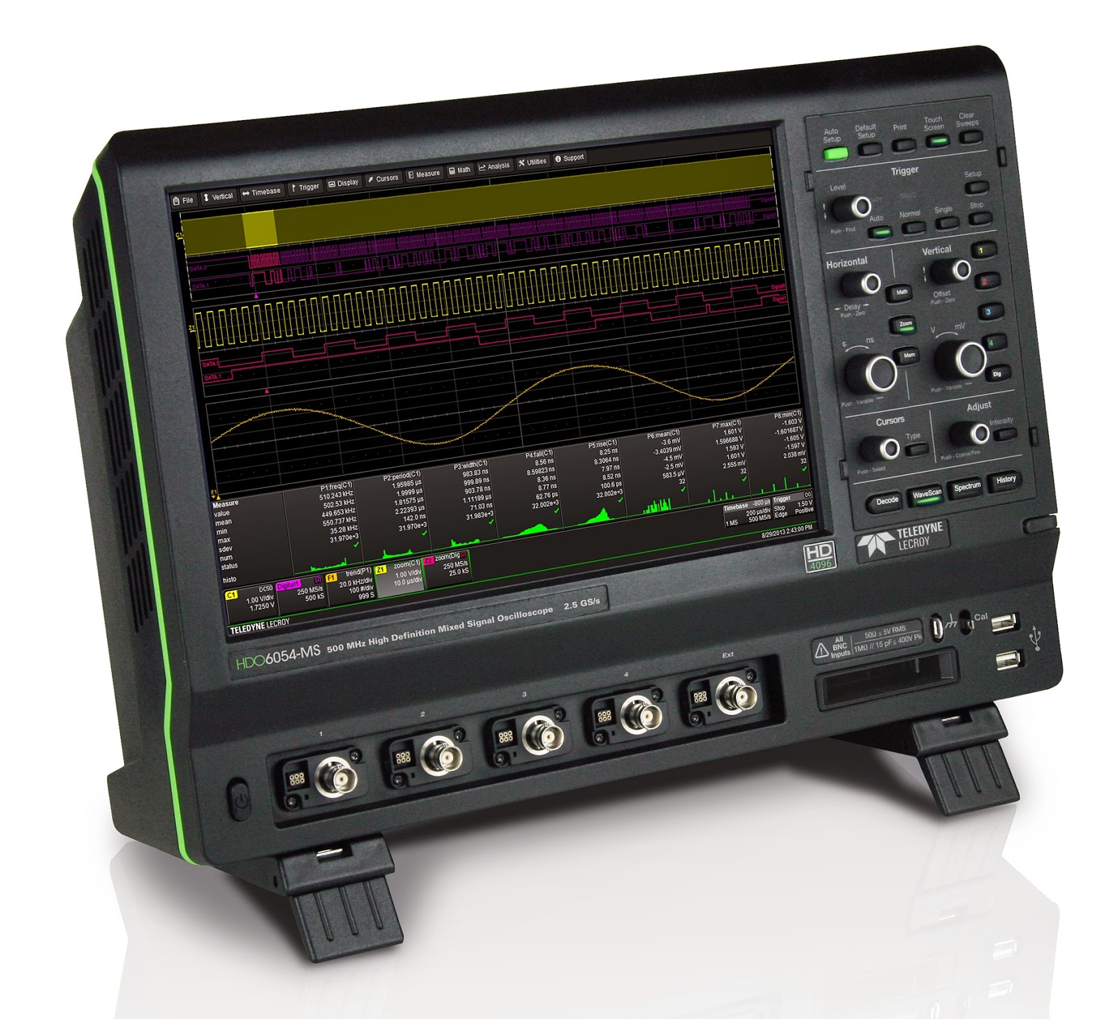
An oscilloscope such as Teledyne LeCroy's HDO6054-MS serves a very broad range of applications
Figure 1: An oscilloscope such as
Teledyne LeCroy's HDO6054-MS
serves a very broad range of
applications
Choosing an oscilloscope might seem to be a challenging task, but it doesn't have to be. Rather, it's a more-or-less logical process based on your measurement needs. Having said that, if the application for the instrument is "general lab work," the decision can become trickier.

20 March 2015

Using Histograms (Part III)
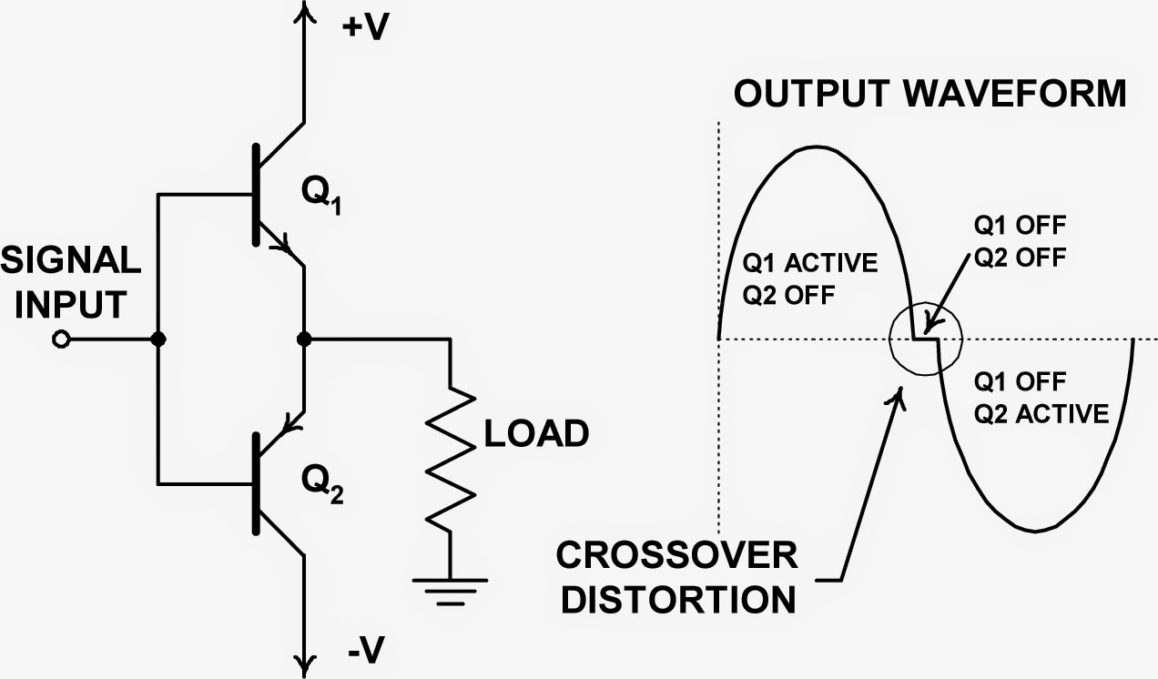
A simplified view of a push-pull amplifier showing the source of crossover distortion
Figure 1: A simplified view of a push-pull amplifier
showing the source of crossover distortion
In this third post in a series on using an oscilloscope's histogram capabilities, let's take a look at using histograms as a diagnostic tool. Diagnosing problems in a circuit calls for good skills and some intuition on top of good measurement tool. In general, though, the more ways in which you're able to look at a problem, the more likely it is that you'll turn up the root cause.

12 March 2015

The History of Jitter (Part II)

An example of using histograms to plot the statistical distribution of edge arrival times
Figure 1: An example of using histograms to plot
the statistical distribution of edge arrival times
Resuming our review of the history of jitter and the evolving response to it, we'd arrived at the late 1990s, when more sophisticated analysis methods were necessary to get a good handle on jitter. In particular, statistical analysis came onto the scene. Statistics are a great tool for analyzing phenomena such as jitter that change more as you look at them harder.

05 March 2015

The History of Jitter

The story of jitter spans 45-baud telegraph machines to 160-Gbaud optical fiber
Figure 1: The story of jitter spans 45-baud telegraph
machines to 160-Gbaud optical fiber
Jitter is a signal-integrity gremlin that's been with us for a long time. In fact, it's been with us since before anyone really needed to care about it. But as time has worn on, our perception of jitter has certainly changed, and with it our approaches to diagnosing it, measuring it, and ultimately dispatching it. Here, we'll begin a traversal of the "jitter story," surveying where we've been, where we are, and where we may be going in our dealings with the phenomenon.

27 February 2015

Using Histograms (Part II)

Figure 1: A flip-flop's propagation delay is a typical spec that can be derived using statistical analysis
Figure 1: A flip-flop's propagation delay is a typical spec
that can be derived using statistical analysis
In Part I of this series, we looked at some of the basics of histograms and how they can provide a statistical view into random variation of signal parameters. Next, let's look at how histograms can help us use statistical analysis to determine product specifications.

09 February 2015

Using Histograms (Part I)

Figure 1: Histograms of the period, width, and TIE show different distributions of time jitter
Figure 1: Histograms of the period, width, and
TIE show different distributions of time jitter
When we measure parameters of a waveform in a circuit or device, we rarely take a single measurement but rather a significant number of measurements. We want to see trends over time in the period, width, and time-interval error of a clock pulse, for example. Those parameters will have some nominal value, but there will typically be some random variation that we refer to as jitter.

30 January 2015

Plan For Successful USB Compliance Testing (Part III)

In USB 3.0 link-layer compliance test, all logical states of the LTSSM come into play
Figure 1: In USB 3.0 link-layer compliance test,
all logical states of the LTSSM come into play
In Part I and Part II of this series on USB compliance test, we've looked at some of the basic information on compliance testing and at some aspects of physical-layer test, respectively. In this third part of the series, we'll turn our attention to USB 3.0 link-layer testing.

26 January 2015

Plan For Successful USB Compliance Testing (Part II)

A representative transmitter compliance test setup
Figure 1: A representative transmitter
compliance test setup
In the first post in this series, we looked at some of the basics of USB 3.0 and 3.1 compliance test and covered the USB-IF's role in overseeing the protocol. Now, let's look into some aspects of physical-layer test.

16 January 2015

Plan For Successful USB Compliance Testing (Part I)

The coveted USB 3.1 logo
Figure 1: The coveted SuperSpeed USB logo
Certifying a device's implementation of a serial protocol standard is a fairly complex process involving a number of levels: electrical test, interoperability, backward compatibility, link layer, and so on. Generally, some organization oversees a given protocol, managing the revision process for the protocol itself as well as the testing process that a product must undergo. Passing the relevant compliance test suite and having a valid Trademark License Agreement on file bestows the prized right to display the protocol's logo on the product's box (Figure 1). That logo's presence tells the product's users that their device's serial interface operates within parameters set by the overseeing organization.