The drive for fuel-efficient and safer vehicles opened the door to electronic control in vehicles, which in turn led to the deployment of In-vehicle Networks (IVN). IVNs have become the backbone of modern vehicles. The volume of data flowing through these networks is increasing exponentially with demands for electric vehicles, advanced driver assistance systems (ADAS), radar, lidar, infotainment systems, cameras and vehicle-to-vehicle communications systems.
To meet this need, the automotive industry—working with technology suppliers—has developed specialized communications protocols and application-specific extensions to existing network technologies, standardized under the aegis of organizations like ISO and IEEE, and it continues to investigate new topologies and protocols to improve performance, increase reliability and lower the costs of IVNs. Two recent developments have filled a longstanding gap in IVN architectures: CAN XL (up-to-20 Mbit/S extended length CAN) and 10Base-T1S (10 Mbit/S single-pair Ethernet), both of which operate in the 10 Mbit/S network space. What problems do these protocols solve and what opportunities do they present for IVN design?
IVNs are organized by a composite architecture combining multiple networks in some logical organization.
 |
| Figure 1. In the Classic IVN architecture, different functional networks utilizing different topologies, protocols and data rates are connected to each other. |
In the Classic architecture, different Engine Control Units (ECUs) all in different locations in the vehicle are connected to each other. Normally, they are placed near to the sensors or the motor depending on the function of the ECU. The result is that everything in the IVN is connected by a huge, heavy and costly cable set.
If we look at the history of IVN protocols used by these ECUs (Figure 2), until recently the pattern shows a concentration of data rates at the low end (under 1 Mbit/S) and at the high end (over 100 Mbit/S). Only FlexRay stood in the mid-range 10 Mbit/S space, and while its characteristic Star topology is very flexible and scalable, FlexRay tends to be more expensive to implement than other automotive protocols, limiting its adoption.
 |
| Figure 2. The history of IVN protocols sorted by data rate. Until recently there was a gap between 1 and 100 Mbps. |
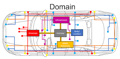
The number of electronic control units (ECUs) in vehicles is continuing to rise. A current mid-range vehicle might have 70 ECUs, while a luxury vehicle might have as many as 150. Connecting these devices is challenging, and vehicle manufacturers seek to consolidate capabilities into fewer devices to reduce complexity and cost. Hence, the evolution of the Domain architecture currently used in newer vehicles.
 |
| Figure 3. In the Domain IVN architecture, domain controllers organize the ECUs under them and communicate with each other through “gateways”. |
The ECUs are more centralized and are divided into functional groups or “domains”. For example, there is one domain for infotainment functions, another domain for the drivetrain, etc., all connected to each other through a gateway. The different domains may use different physical layers, which means different bus systems. Some may use Ethernet while others use CAN. The gateway handles translation between the different domains and ensures smooth, safe and correct communication between all ECUs.
The “next generation” IVN architecture is called Zonal architecture. In the Zonal architecture, main controllers called zone controllers are located in different sections of the car (e.g., front left, front right). The sensors and actuators are connected directly to the zone controller, and because the zone controller is close to the interfaced devices, the cable lengths required to connect them are relatively short, resulting in less weight and expense. This architecture reduces the number of wires in the harness, and there are fewer ECUs overall replaced by much more powerful, centralized ECUs for the different regions of the car.
A central controller connected to the zone controllers over a high-speed data “backbone” performs data fusion and higher level decision making functions. The backbone also serves to provide the data redundancy needed especially for autonomous driving. Because of the volume of data exchanged between the controllers, as well as the need to connect to external high-speed networks, higher speed and higher throughput are essential to this architecture, especially for the central controller and backbone functions. It is necessary to be able to move data at speeds well above 10 Mbit/S.
All IVN designs involve multiple buses because some operations do not require a high data rate and the attendant bandwidth, as shown in Figure 5. The power train or body/comfort domains are normally slower networks. In most current architectures, only a limited number of functions, like infotainment or ADAS systems, absolutely require high bandwidth. Some functions that do not need a high data rate are very important nonetheless and need a high priority. For example, safety functions require a very high priority, but only have a medium bandwidth requirement. So, for many functions, a data rate of 10 Mbit/S is as high as required. Yet, until recently, few protocols operated in the gap between 1 and 10 Mbit/S.
 |
| Figure 5. A summary of vehicular network requirements by function. |
CAN FD with a maximum data rate of 5 Mbit/S was an early attempt to close that gap. The more recent entries to fill the data rate gap are CAN XL (extended length CAN), which operates up to 20 Mbit/S in the data phase, and 10Base-T1S (10Mbit/s single-pair Ethernet), which operates at a maximum rate of 10 Mbit/S.

No comments:
Post a Comment