 |
| Figure 1: Interleaved decoding of USB-PD and DP-AUX signals. |
The USB-C connector packs many protocols onto one, small pin set, and maintaining signal and power integrity is a compliance challenge. Besides high-speed data delivery, USB-PD (power delivery) provides flexible power distribution, while auxiliary sideband signals, like DisplayPort™, transport video. Troubleshooting these capabilities requires the ability to measure timing between serial data packets, as well as between data packets and analog signals.
For example, DisplayPort over USB-C (DPoC) in alternate mode (alt-mode) can manifest as an interoperability failure if there is a timing issue between alt-mode initiation and the start of DP-AUX.
An approach to verifying the timing is to simultaneously acquire the USB-PD and DP-AUX signals through a USB-PD Coupon (such as TF-USB-C-SB or TF-USB-C-HS), which provides probing points for the USB-PD CC1/CC2 and SBU pins on any device connected through a USB-C cable. The coupon also provides access to VBUS and a current loop for measuring the current on VBUS for debugging power delivery issues.
In Figure 1 we show the USB-PD CC1 line probed using a high-impedance passive probe and displayed on oscilloscope C1 (upper left grid). The DP SBU line is probed differential and displayed on C4 (lower left grid). Simultaneously acquiring and decoding both signals using our USB-PD TDME and DPAux D options creates a color-coded, time-correlated, interleaved table of packets that immediately shows relative timing between messages.
By using the USB-PD TDME symbolic decoding capabilities, we can access payload data in real-world terms, such as “SVID”. That allow us to search the USB-PD table Bit Description column for the value “SVID= 0xff01”, which is the SVID for DisplayPort. This is the final message before alt-mode is initiated, so zooming to this message within the USB-PD decoding (upper right) will automatically zoom the DPAux decoding (lower right), as well, and show us exactly when DP-AUX is initiated.
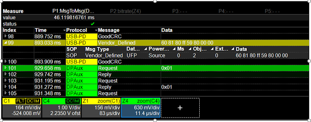
The next step is to apply the TDME Measure/Graph capabilities to the decoding, as shown in Figure 2. The Message-to-Message automated timing measurement ascertains exactly how much time elapsed between the start of the USB-PD message in one decoder and the start of the DP-AUX message in the other decoder.
 |
| Figure 2: P1 shows timing between the USB-PD and DPAux messages. (Note the decoding was changed to hexadecimal to make room for the Measure table.) |
This measurement is applied to the protocol decodes, not the physical layer waveforms: we are looking at the time delay between two messages in two different protocols. The measurement result is output to the Measure table parameter P1. The time between this alt-mode message and DP-AUX starting is 46 milliseconds. It is this latency which may the source of the interoperability failure.
We could go a step further and set up our own “pre-compliance” test by setting a Pass/Fail test on the result of the Message-to-Message parameter, using the standard compliance limit or any other limit we wished. That way, we could run a continuous acquisition, and whenever the elapsed time exceeded the limit, we could be warned in any number of ways, such as having the acquisition stop so we can see exactly which packets are causing problems, and correlate this to other things that may be occurring at that time. Up-to-four signals could be decoded at once, and multiple serial data measurements or Pass/Fail tests applied to the interactions between them.
You can watch Mike Engbretson demonstrate this and other USB-C test approaches in the on-demand webinar, USB-C Physical Layer Testing.
Also visit our USB Electrical Test page for more information about our other USB test solutions.
No comments:
Post a Comment