 |
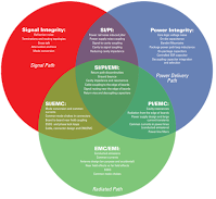
| Figure 1: The holistic view of power integrity |
It's equally important to approach power integrity the way you would approach any other design/debug task: methodically and with a dash of skepticism. Here are three key principles to apply:
- The fastest way to solve a problem is to identify the root cause. Failing that, you're depending on luck.
- Have a clue (also known as "Dr. Eric Bogatin's Rule #9"): Whenever you make a measurement, you must have some idea of what you should expect as a result. If you're wrong, the fault lies either in your setup or your intuition. The late Bob Pease, analog guru at National Semiconductor and famously opinionated industry columnist, was suspicious of Spice simulation for this reason. Too often, he claimed, engineers would run Spice without any sort of anticipation of what the results should be, and would let the tool lead them in the wrong direction in their search for the solution to a problem.
- Measurements help us confirm reality. It's a good habit for engineers to verify the specifications of a DUT by direct measurements. Documentation isn't always accurate.
With the above in mind, let's look at what's meant by a "holistic" approach to power integrity (Figure 1). Within a system, there are three "worlds" or domains that we are concerned with: signal integrity (the signal path), power integrity (the power-delivery path), and EMC/EMI (the radiated path). These domains, of course, interact with each other in a complicated matrix of effects.
First, let's look at the three domains individually. In the signal-integrity sphere fall the following effects and/or problem areas:
The interactions of these domains results in some gnarly results. To wit, the intersection of the signal-integrity and power-integrity domains creates the following:
The power-integrity and EMC/EMI domains spawn some troublesome areas of their own:
Having outlined the approach one should take to power-integrity measurements and taken a top-level look at the problems that power integrity entails, we'll continue with a review of the power-distribution network and why PDN design is so difficult. You can also view our power integrity webinars at any time for additional insight.
Figure courtesy of Signal Integrity Journal:
(https://www.signalintegrityjournal.com/ext/resources/SIJ-2018-Media-Kit/SIJ-MEDIA-KIT-2018.pdf)
For more on the power-integrity measurement mindset, see Signal and Power Integrity for PDN Design Simplified, 2nd Edition, by Eric Bogatin and Larry Smith, Prentice Hall, 2017
First, let's look at the three domains individually. In the signal-integrity sphere fall the following effects and/or problem areas:
- Reflection noise
- Terminations and routing topologies
- Crosstalk
- Attenuation and loss
- Mode conversion
Power-integrity effects and potential pitfalls include:
- Core logic voltage noise
- On-die capacitance
- Bandini mountains
- Package power-path loop inductance
- On-package capacitors
- Controlled ESR capacitor
- Decoupling capacitor integration and selection
The third domain, EMC/EMI, has its own gremlins:
- Conducted emissions
- Common currents
- Antenna design (both intentional and unintentional)
- Near-field effects vs. far-field effects
- Spread-spectrum clock generation (SSCG)
- Common-mode chokes
- Power rail noise-induced jitter
- Power-supply noise coupling
- Signal-to-cavity coupling
- Cavity-to-signal coupling
- Reducing cavity impedance
Signal-integrity and EMC/EMI issues can include:
- Mode conversion and common currents
- Common-mode chokes in connectors
- Board-to-board near-field coupling
- SSCG and phase-lock loops
- Cable/connector design and EMI/EMC
- Cavity resonances
- Radiation from board edges
- Power-supply design and large-current transients
- Common currents in power lines (conducted emissions)
- Power-line filters
At the center of a Venn diagram of all three of these domains is the sum of their combined effects and/or the problems they combine to create:
- Return-path discontinuities
- Ground bounce
- Cavity impedance and resonances
- Cable coupling to the edges of boards
- Signal routing near the edge of boards
- Return vias and decoupling capacitors
Figure courtesy of Signal Integrity Journal:
(https://www.signalintegrityjournal.com/ext/resources/SIJ-2018-Media-Kit/SIJ-MEDIA-KIT-2018.pdf)
For more on the power-integrity measurement mindset, see Signal and Power Integrity for PDN Design Simplified, 2nd Edition, by Eric Bogatin and Larry Smith, Prentice Hall, 2017
No comments:
Post a Comment