You need to test, we're here to help.

You need to test, we're here to help.

29 June 2018

The Effects of De-Emphasis on Eye Diagrams

This "at the receiver" eye diagram of a serial-data stream shows the effect a lossy channel has on signal quality
Figure 1: This eye diagram of a serial-data stream as measured
at the receiver shows the effect a lossy channel has
on signal quality
Having discussed what transmit pre-emphasis is all about and the various ways in which it's implemented, it might be useful at this juncture to look at some examples of its application and the salutary effect it can have on the signal's eye diagram at the receiver end of the channel. Recall that there are two variations on pre-emphasis: de-emphasis and pre-shoot, which use different taps of a three-tap finite impulse response (FIR) filter to emphasize the last bit or the first bit of a bit sequence, respectively.

27 June 2018

Introduction to Channel Equalization

Transmit pre-emphasis pre-distorts signals in anticipation of the channel's effects
Figure 1: Transmit pre-emphasis pre-distorts signals
in anticipation of the channel's effects
A number of factors can cause degradation of performance in a high-speed serial data link. Among them are inter-symbol interference (ISI) jitter, attenuation, reflections due to impedance mismatches, and insertion losses, to name a few. But fear not: There are techniques one may use to compensate for these losses known as equalization. We'll review the basics of channel equalization in today's post.

19 June 2018

Rise-Time Degradation and ISI Jitter

Shown are the signals from two extreme bit patterns overlaid on top of each other with no interconnect in the channel
Figure 1: Shown are the signals from two extreme bit patterns
overlaid on top of each other with no interconnect in the channel
In discussing inter-symbol interference (ISI), the phenomenon in which information "leaks" from one bit to subsequent bits, we've identified a couple of root causes of ISI jitter. The first is reflection losses caused by impedance discontinuities, while the second is group delay dispersion, a consequence of the differing propagation speeds of different frequencies through a given material. We looked at these forms of distortion in both the time and frequency domains.

13 June 2018

Inter-Symbol Interference (or Leaky Bits)

Inter-symbol interference, or ISI jitter, is the result of information from one bit "leaking" to subsequent bits
Figure 1: Inter-symbol interference, or ISI jitter, is the result
of information from one bit "leaking" to subsequent bits
In reviewing the subject of debugging high-speed serial links, one important aspect of signal integrity we must touch on is inter-symbol interference (ISI). ISI is the phenomenon in which information from one bit "leaks" to some subsequent number of bits.

12 June 2018

How Much Transmission-Line Loss is Too Much?

This plot represents the differential insertion-loss profile for a 20" FR-4 microstrip trace
Figure 1: This plot represents the differential insertion-loss
profile for a 20" FR-4 microstrip trace
One of the fundamental facts of transmission lines is losses. Any effort to debug the performance of a high-speed serial data link begins there. But it begs an equally fundamental question: How much loss in a transmission line is too much? How do we quantify losses, and what is the connection between attenuation at the Nyquist frequency and the eye diagram? Is there a rule of thumb one might apply, some sort of rough estimate of how much loss might be too much for your channel to bear at a given data rate?

06 June 2018

A Look at Transmission-Line Losses

Using a 3D field solver to simulate a differential trace
Figure 1: Using a 3D
field solver to simulate
a differential trace
In surveying the subject of debugging high-speed serial data links, we've noted that there's no one cause for signal-integrity issues between transmitter and receiver, and there's certainly no one solution. But let's begin with the low-hanging fruit: electrical losses in the transmission line. We've previously done a series of posts on transmission lines (beginning here), but it's worth it to have a quick refresher.

05 June 2018

Introduction to Debugging High-Speed Serial Links

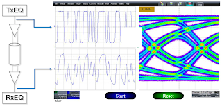
These images depict the degradation of serial data traffic as it makes its way from transmitter to receiver
Figure 1: These images depict the degradation of serial data
traffic as it makes its way from transmitter to receiver
In recent years, the data rates in serial links have increased exponentially across any number of standard protocols, including PCI Express, USB, and even SATA and SAS. With higher data rates comes more challenges for system designers, validation engineers, and test engineers with respect to signal integrity (SI). Some SI effects are much more prominent at higher data rates than they were for lower-speed versions of the same protocols. In this series of posts, we'll examine these SI effects, look at some methods of improving system performance, and discuss some SI analysis solutions as well as measurement considerations.